Method for removing liquid from a slurry

a technology of liquid removal and slurry, which is applied in the direction of presses, manufacturing tools, separation processes, etc., can solve the problems of affecting the quality of the material, the material is too thin, and the wear of the press increases quickly, so as to reduce the risk of material damag

Active Publication Date: 2015-06-18
IOGEN ENERGY CORP +1
View PDF8 Cites 5 Cited by
  • Summary
  • Abstract
  • Description
  • Claims
  • Application Information

AI Technical Summary

Benefits of technology

[0010]According to one aspect of the invention, there is provided a method for removing liquid from a slurry using a press comprising an inlet, a deliquifying section, a plug section, a plug discharge section, an outlet and a conveyance member mounted axially in the press for advancing material therethrough. According to the invention, the press is operated so that the pressure within the discharge section of the press is greater than the pressure of a pressate stream produced in the deliquifying section of the press. This produces a plug of material having reduced liquid content. By operating the press so that there is a pressure differential between the pressate stream and the discharge section, the discharge consistency can be controlled without requiring complex mechanical devices for this purpose, such as variable discharge restrictors.

Problems solved by technology

If material discharged from a press is too thick, wear on the press increases quickly as well as the load on the motor.
Increases in discharge consistency may also lead to plugging of the press or downstream equipment.
Conversely, material that is too thin may increase chemical and steam usage.
Although the material discharged from the press can be evaporated or dilution liquid can be added to the discharged material to reach a desired consistency, these additional operations add cost to the process.
Flow restriction devices partially obstruct the flow of the plug from the discharge end of the press.
Although these mechanical designs can control the discharge consistency from the press within a set range, they add mechanical complexity.
This increases capital costs and requires increased maintenance.

Method used


Image

  • Method for removing liquid from a slurry
  • Method for removing liquid from a slurry

Examples


Embodiment Construction

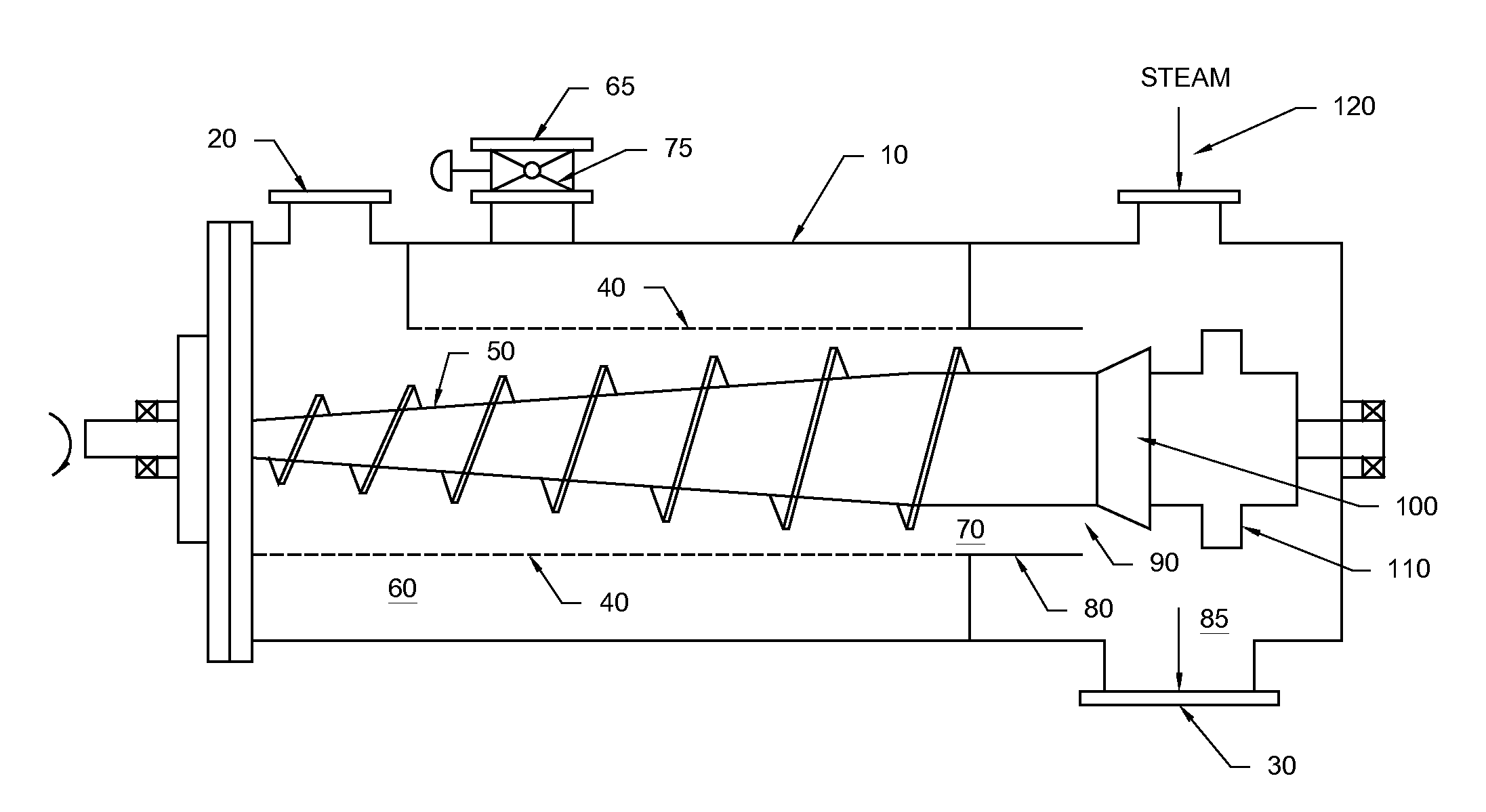
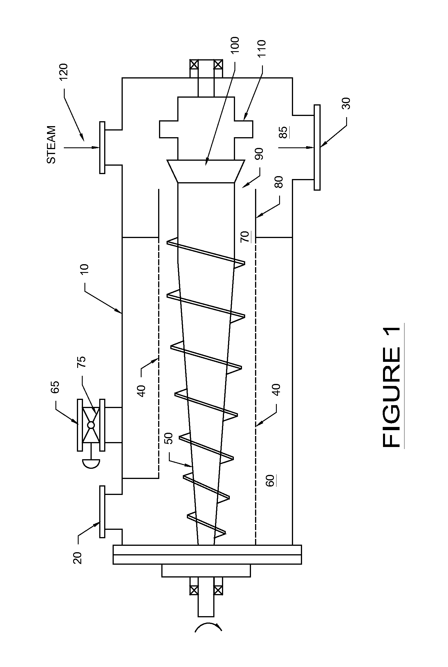
[0025]The following description is of a preferred embodiment by way of example only and without limitation to the combination of features necessary for carrying the invention into effect.

Slurry Preparation

[0026]The slurry from which liquid is removed in accordance with the invention may include organic material or materials derived from inorganic sources. Preferably, the slurry comprises organic material, which may be of plant and / or animal origin. The plant derived organic material may comprise polysaccharides, including cellulose and hemicellulose and starch, oligosaccharides, disaccharides, monosaccharides, or a combination thereof.

[0027]Preferably, the slurry is a lignocellulosic feedstock slurry. By the term “lignocellulosic feedstock”, it is meant any type of woody or non-woody plant biomass, or feedstock derived from plant biomass, such as, but not limited to, dedicated biomass crops such as, but not limited to grasses, for example, but not limited to, C4 grasses, such as swi...


PUM


Abstract

The method includes the following steps: (i) feeding a slurry into the inlet of a press; (ii) removing liquid from the slurry as the slurry advances through a deliquefying section of the press, thereby producing a pressate stream; (iii) forming a plug of material as the slurry is advanced through a plug formation section of the press; (iv) advancing the plug of material to a discharge section of the press; and (v) removing additional liquid from the plug of material by operating the press so that the pressure in the discharge section of the press is greater than the pressure of the pressate stream by at least 2 psi. There is also described a method for controlling discharge consistency from a press, without provision of discharge restrictors, by varying a pressure differential between a discharge section of the press and a pressate stream.

Description

TECHNICAL FIELD[0001]The present invention relates to an improved method for removing liquid from a slurry. In particular, the present invention relates to an improved process for removing liquid from a slurry using a press.BACKGROUND OF THE INVENTION[0002]Slurries are processed in many industries ranging from food processing to biofuel production. In the production of biofuels, for example, the addition of water or other liquid to the incoming feedstock to form a slurry facilitates the transportation and mechanical handling of the feedstock.[0003]There has been impetus in many industries in recent years to reduce the liquid content of slurries to improve process economics. Processing of slurries with low liquid content can considerably reduce energy and chemical usage in a plant. For example, in ethanol production, feedstock slurries can be deliquified prior to energy intensive operations such as heating of the feedstock slurry, which is employed in a cooking operation conducted wi...

Claims


Application Information

Patent Timeline
Patent Type & Authority Applications(United States)
IPC IPC(8): B30B9/12B30B9/18B30B9/14
CPCB30B9/125B30B9/18B30B9/14B30B9/127B30B9/12C02F11/125Y02E50/10
Inventor MILLER, WILLIAMRICHARDSON, TREVORROWLAND, STEPHEN A.
Owner IOGEN ENERGY CORP
Why Eureka
Try Eureka