Fluid characteristic indicator
- Summary
- Abstract
- Description
- Claims
- Application Information
AI Technical Summary
Benefits of technology
Problems solved by technology
Method used
Image
Examples
embodiment 170
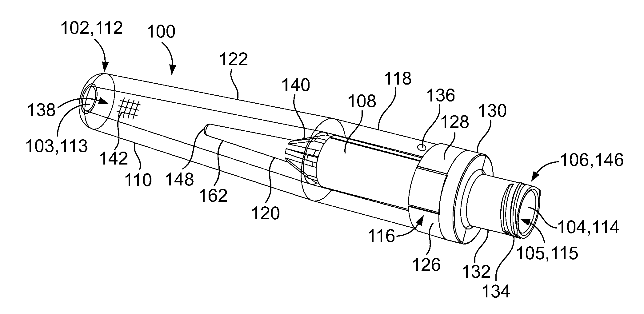
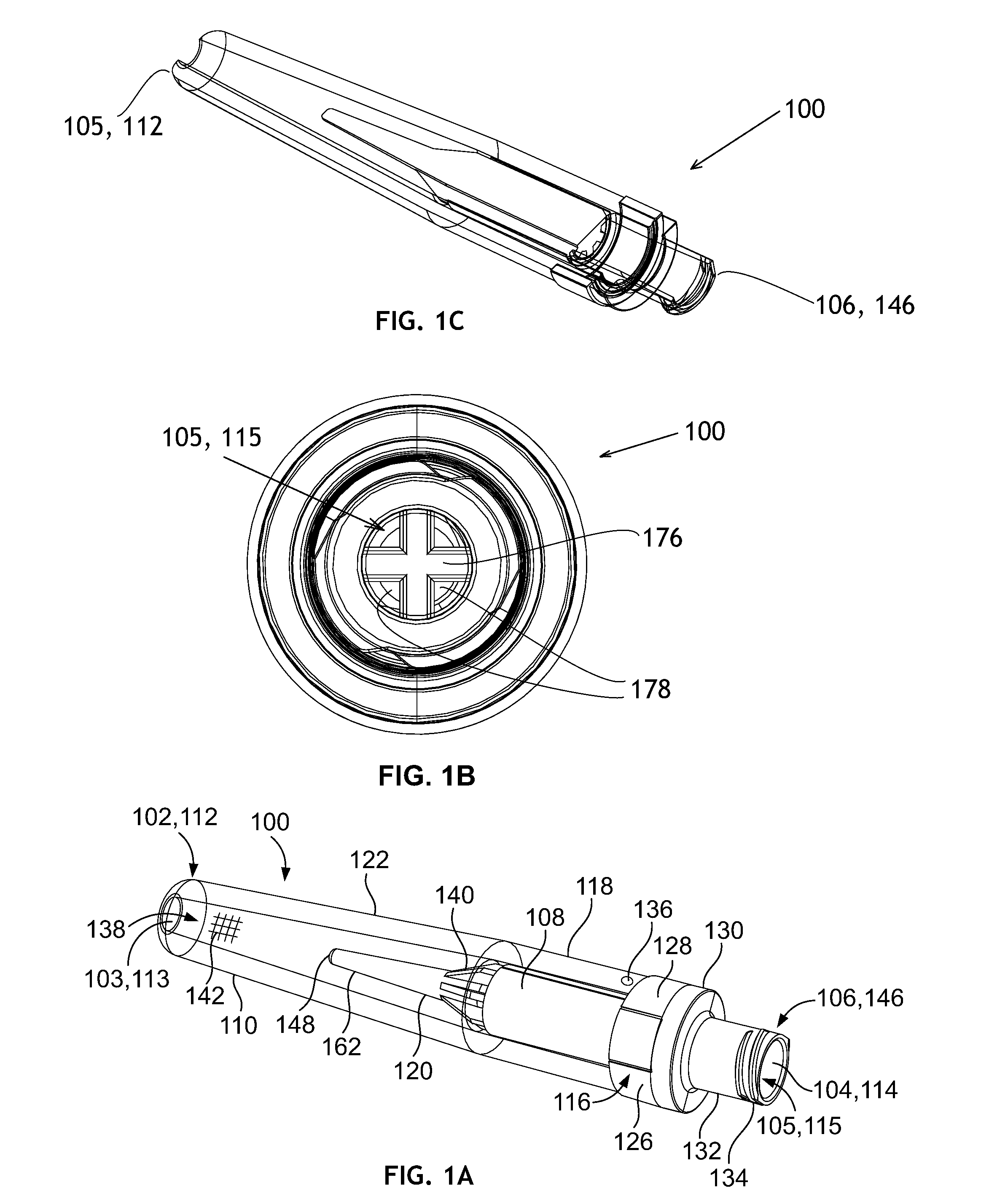
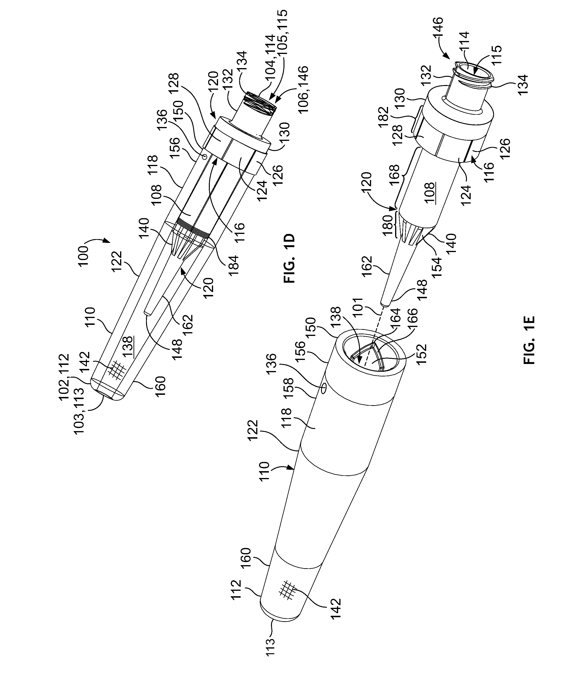
[0090]Although housing 110 is depicted in FIGS. 1A-1E, with a “catheter tip” distal end 112 configuration that accommodates frictional, sealing engagement with the fluid transport source, housing 110 could also have another structure for coupling to the fluid transport source. FIG. 2A is a side view of an embodiment 170 of a housing constructed in accordance with a further aspect of the present invention. Housing 170 is generally similar to the housing 110 of FIGS. 1A-1E, but has a male Luer lock fitting 174 at the distal end 172, instead of the catheter tip. Housing 170 is generally similar to housing 110 of FIGS. 1A-1E as heretofore described, and except for the differences explained below, the foregoing description of housing 110 housing 170, mutatis mutandis, and is hereby incorporated by reference. The Luer lock 174 may mate with a complementary fitting on the fluid transport source. The positive mating avoids the need to rely on friction alone for a seal and may avoid malfunct...
embodiment 190
[0097]FIG. 2B is an isometric view, and FIG. 2C is a side view, of a further embodiment 190 of a housing which is similar to the housing 110 of FIGS. 1A-1E but which provides a central fluid passage 192 of modified cross section. Housing 190 is generally similar to housing 110 of FIGS. 1A-1E as heretofore described, and except for the differences explained below, the foregoing description of housing 110 is applicable to housing 190, mutatis mutandis, and is hereby incorporated by reference. A fluid passage 192, which functions in a manner similar to the fluid passage 138 of the housing 110 of FIGS. 1A-1E extends between a distal-end or intake port 198 and a proximal end opening 188. FIG. 2D is a view of housing 190 looking into the proximal end opening 188 as shown by view lines 2D-2D of FIG. 2C. FIG. 2E is a view of housing 190 looking into the distal end opening 198 as shown by view lines 2E-2E of FIG. 2C. FIG. 2F is a cutaway view of the housing 190 of FIGS. 2B and 2C, taken alon...
embodiment 120
[0105]In an embodiment 120 of a diffuser constructed according to one aspect of the invention, the indicating element section 168 may have a generally star-shaped cross-section formed by spines, ridges, or vanes 140 extending radially from a central core along the length of indicating element section 168. The vanes 140 further extend longitudinally between the indicating element section 168 to the tip section 162 through the second transition section 180, tapering in diameter. The configuration of vanes 140 form plural substantially independent diffuser fluid channels 154, which may be used to independently expose different indicating elements 108 or portions thereof. The plural independent diffuser fluid channels 154 could also be used to route fluid from different respective fluid sources to one or more indicating elements; a modification of the housing would be needed to receive fluid from plural sources and separately convey the fluid to respective fluid channels. Other diffuser...
PUM
 Abstract
Description
Claims
Application Information
 - R&D
- Intellectual Property
- Life Sciences
- Materials
- Tech Scout
- Unparalleled Data Quality
- Higher Quality Content
- 60% Fewer Hallucinations
Browse by: Latest US Patents, China's latest patents, Technical Efficacy Thesaurus, Application Domain, Technology Topic, Popular Technical Reports.
© 2025 PatSnap. All rights reserved.Legal|Privacy policy|Modern Slavery Act Transparency Statement|Sitemap|About US| Contact US: help@patsnap.com


