Scintillating Fiber Dosimeter for Magnetic Resonance Imaging Enviroment

a magnetic resonance imaging and fiber dosimeter technology, applied in the direction of radiation intensity measurement, instruments, x/gamma/cosmic radiation measurement, etc., can solve the problems of limited precision, temperature dependence, electromagnetic fields can create havoc with relatively faint electrical signals, etc., to minimize interaction and low interactivity

Inactive Publication Date: 2015-06-18
STANDARD IMAGING
View PDF1 Cites 7 Cited by
  • Summary
  • Abstract
  • Description
  • Claims
  • Application Information

AI Technical Summary

Benefits of technology

[0007]The present invention provides an x-ray detector that may be used with magnetic resonance imaging systems, Specifically, the detection system employs a fiber optic scintillation detector constructed of non-ferromagnetic electrically insulating materials that offers low interactivity with electromagnetic fields of the MRI device. The present inventors have determined that the fiber optic allows the detection electronics of the detection system to be sufficiently displaced from the imaging field of the MRI machine to acceptably minimize interaction with the field of the MRI machine. The use of ferromagnetic components in the detection electronics is also minimized.
[0008]One embodiment of the invention provides a radiation detector having a detection optical fiber communicating with a scintillating material responsive to radiation at a distal end and having a light detecting module communicating with the proximal end of the detection optical fiber to receive light through the detection optical fiber from the scintillating materials, the light detecting module providing at least one photodetector. A shielded cable communicates with the photodetector and is adapted to conduct an electrical signal from the photodetector to an electronic display remote from the photodetector. The light detecting module and shielded cable are substantially free from ferromagnetic materials.
[0009]It is thus a feature of at least one embodiment of the invention to practically integrate an x-ray detector into the MRI environment without the distortion of the MRI image for the generation of destructive eddy current flows that can occur with ferromagnetic or conductive materials.

Problems solved by technology

Such films may be used to assess radiation patterns and intensities but are subject to a number of drawbacks including temperature dependencies and limited precision.
These electromagnetic fields can create havoc with relatively faint electrical signals produced by conventional electronic radiation detectors such as ion chambers and semiconductor devices.

Method used


Image

  • Scintillating Fiber Dosimeter for Magnetic Resonance Imaging Enviroment
  • Scintillating Fiber Dosimeter for Magnetic Resonance Imaging Enviroment

Examples


Embodiment Construction

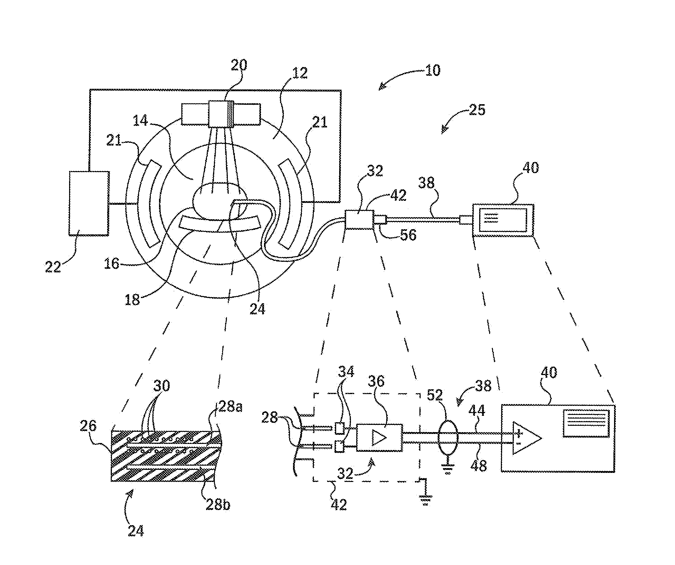
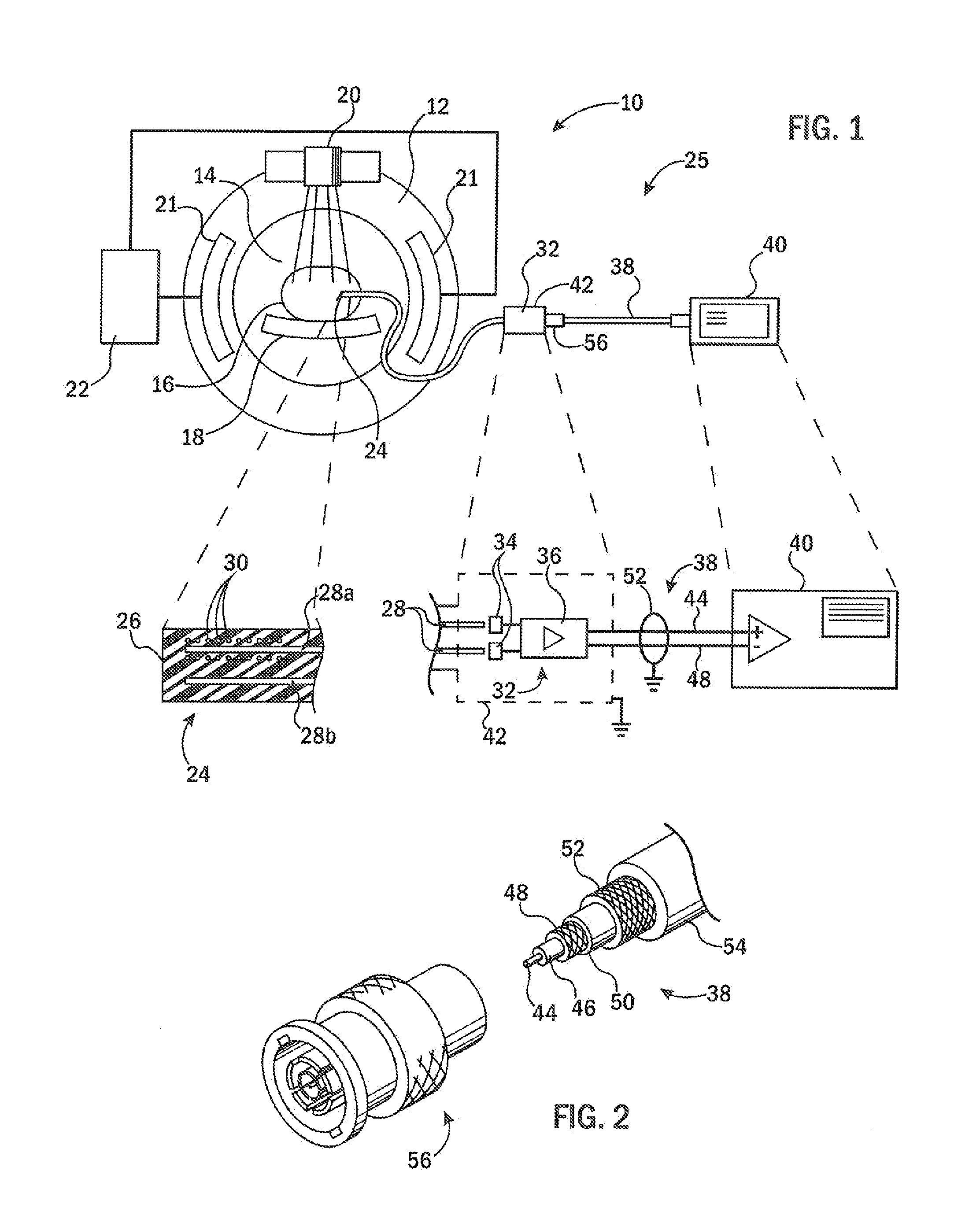
[0033]Referring now to FIG. 1, an MRI machine 10 may include a magnet 12 producing a polarizing magnetic field (for example, generally directed out of the page) typically in the range of one or more Tesla within an imaging region 14 of the MRI machine 10. The imaging region 14 may hold a patient 16 supported within the imaging region 14 on a patient table 18. Radiofrequency coils 21 of the MRI machine 10 are positioned adjacent to the imaging region 14 as shown or placed directly on the patient and are driven by radiofrequency amplifier / detector circuitry 22.

[0034]During operation of the MRI machine 10, the radiofrequency amplifier / detection circuitry is operated to stimulate the precession of protons within patient tissue. This precession, as modified by various magnetic gradient coils. may then be detected by the radiofrequency coils 21 (or other coil structures) to produce an MRI image of the patient 16 within the imaging region 14.

[0035]The MRI machine 10 may include or be used ...


PUM


Abstract

An x-ray detector for use in the presence of magnetic resonance imaging equipment provides a two-stage transmission path of optical fiber followed by a non-ferromagnetic shielded cable to displace measurement electronics outside of the concentrated magnetic and radiofrequency fields of the MRI device. Conversion from light to an electrical signal for this transmission path is provided by circuitry held in a non-ferromagnetic Faraday cage. In this way accurate x-ray measurements may be made in radiotherapy equipment working in conjunction with magnetic resonance imaging for accurate dose placement.

Description

CROSS-REFERENCE TO RELATED APPLICATIONS[0001]This application claims the benefit of U.S. provisional application 61 / 917,544 filed Dec. 18, 2013, and hereby incorporated by reference.BACKGROUND OF THE INVENTION[0002]External beam radiation therapy systems provide beams of high energy directed into a patient to treat tumors or the like. The size, location, angle and intensity of the beams are determined by a treatment plan which is based on known information about the pattern (intensity and distribution) of radiation produced by a particular radiation therapy machine.[0003]Quantitative accuracy in the dose produced by the radiation plan requires accurate characterization of the radiation therapy machine. This characterization is normally done by making periodic measurements of the radiation beam using a single or multiple radiation detectors positioned in phantoms mimicking human tissue.[0004]One type of radiation detector is a radiographic or radiochromic film. Such films may be used...

Claims


Application Information

Patent Timeline
Patent Type & Authority Applications(United States)
IPC IPC(8): G01T1/105G01T1/20
CPCG01T1/2002G01T1/105G01T1/1603G01T1/20
Inventor HOOTEN, BRIAN DOUGLASBONDE, THOMAS CHRISTOPHER
Owner STANDARD IMAGING
Why Eureka
Try Eureka