On-Patient Autonomous Blood Sampler and Analyte Measurement Device

an autonomous, blood sampler technology, applied in the field of on-patient autonomous blood sampler and analyte measurement device, can solve the problems of increasing healthcare costs, reducing the clinical value of blood samplers, and reducing the clinical value of patients, so as to improve the clinical value and improve the clinical value. the effect of ecgs and the increase of the surface area of the electrod

Inactive Publication Date: 2015-07-02
CARDIOCANARY
View PDF3 Cites 13 Cited by
  • Summary
  • Abstract
  • Description
  • Claims
  • Application Information

AI Technical Summary

Benefits of technology

[0020]The invention also relates to a method of fabrication that enables a significant increase in the surface area of the electrode when compared to conventional silicon electrodes of the same footprint. Three dimensional sensing electrodes are silicon-based metal sputtered electrochemical electrodes with larger surface area than conventional silicon electrodes of the same footprint. The increase in surface area may be two-fold to several hundred-fold. The larger surface area is made possible by etching a series of vertical trenches into the silicon substrate. Trenches may be created using a number of processes, including but not limited to mechanical dicing, photo patterning and ion etching, etc. Variability in surface area is minimized due to the precision of the manufacturing processes. The silicon substrate may be sputtered with gold, platinum, or any other appropriate electrically conductive material to create electrodes.
[0021]It is a goal of the invention to shift the clinical practice paradigm through the automation of the entire process of diagnostics: biological sample acquisition through testing all the way to result communication. For example, multiple tests for cardiac troponin, or any other blood analyte, can be run at pre-determined frequencies using a single disposable cartridge. The patient-centric solution can drive a 10-fold improvement in test-order-to-test-result turnaround time. This streamlined system coul

Problems solved by technology

For the vast majority of the rest of these patients, the challenge is to rapidly triage them to determine which 10-15% need immediate intervention and which can be safely discharged.
This is especially significant for cases where electrocardiograms (ECGs) are non-diagnostic.
Additionally, holding patients in the ER for the hours it takes to complete the protracted sequence of tests contributes greatly to ER overcrowding and increased healthcare costs.
Unfortunately, accelerated serial measurement has not been adopted in emergency departments due to their inability to perform higher frequency testing using existing protocols, personnel and equipment (central laboratory and point-of-care instruments).
Given that every year over 8 million Americans are

Method used


Image

  • On-Patient Autonomous Blood Sampler and Analyte Measurement Device
  • On-Patient Autonomous Blood Sampler and Analyte Measurement Device
  • On-Patient Autonomous Blood Sampler and Analyte Measurement Device

Examples


example 1

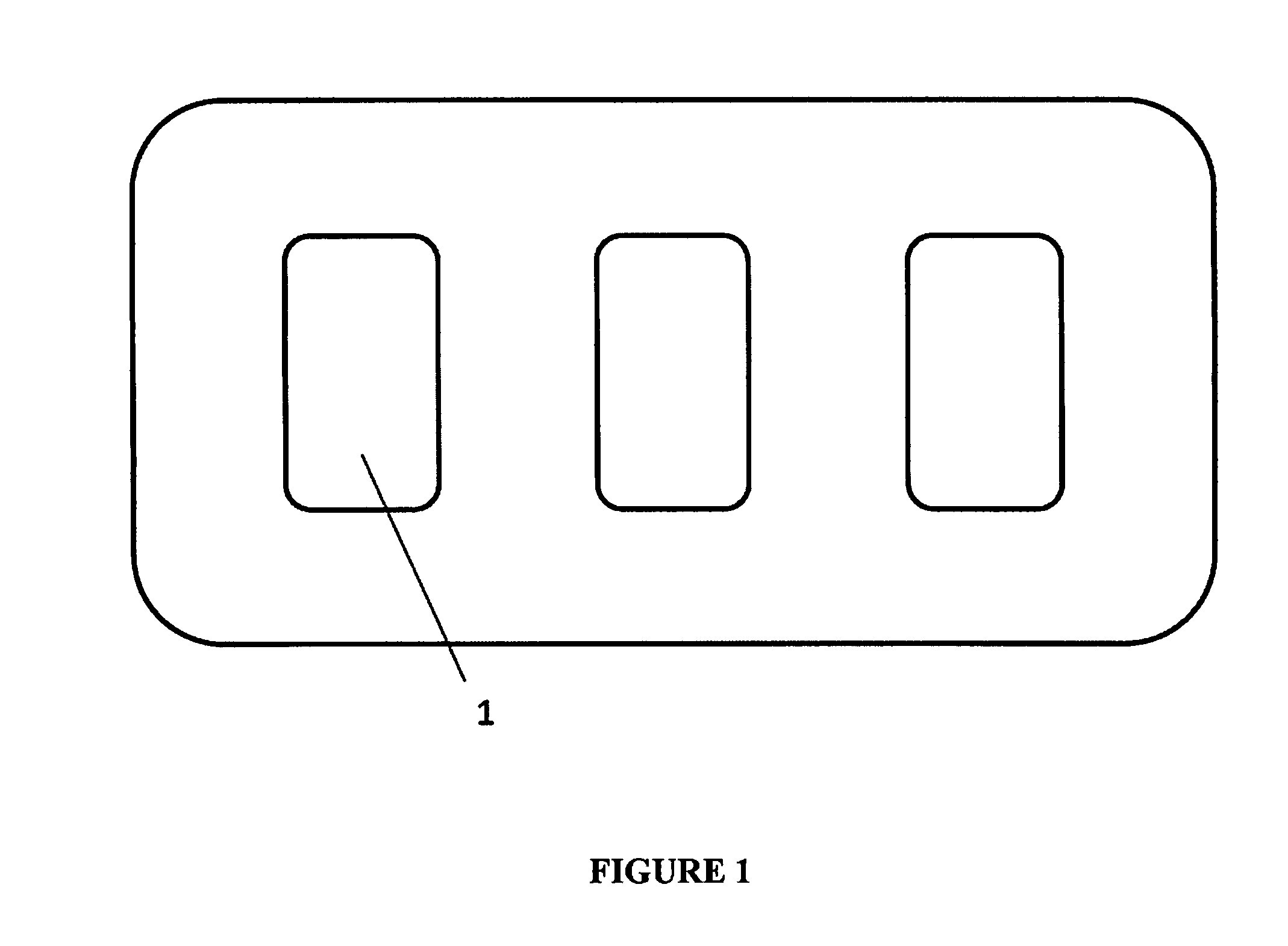
[0091]One embodiment of the apparatus of the invention comprises a disposable cartridge. FIG. 1 shows a top view of this embodiment having three individual assay units. Each assay unit [1] has its own piercing element, piercing mechanism, biosensor fluidic circuit, mechanism for generating vacuum or suction, means of moving fluid through the biosensor fluidic circuit, reservoir for collecting waste fluids, chemical reagents, biological reagents, buffers, reaction solutions, and electrodes.

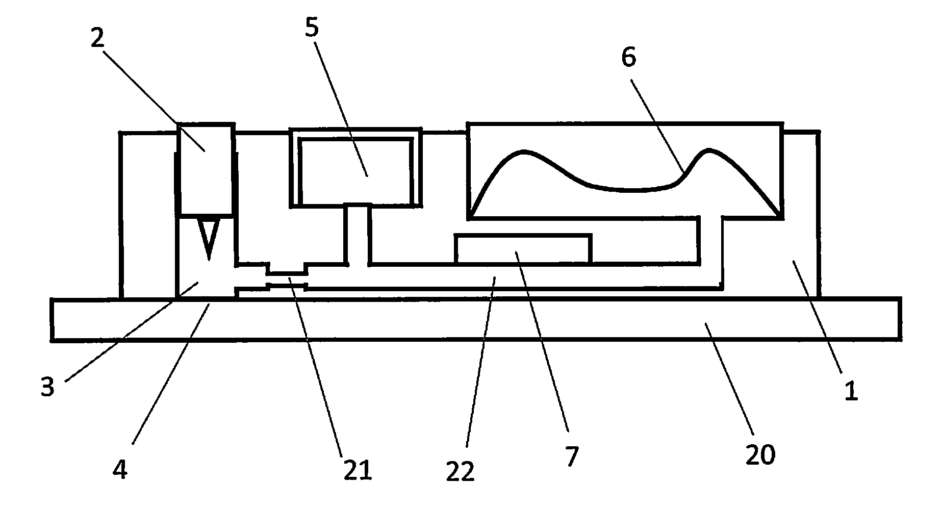
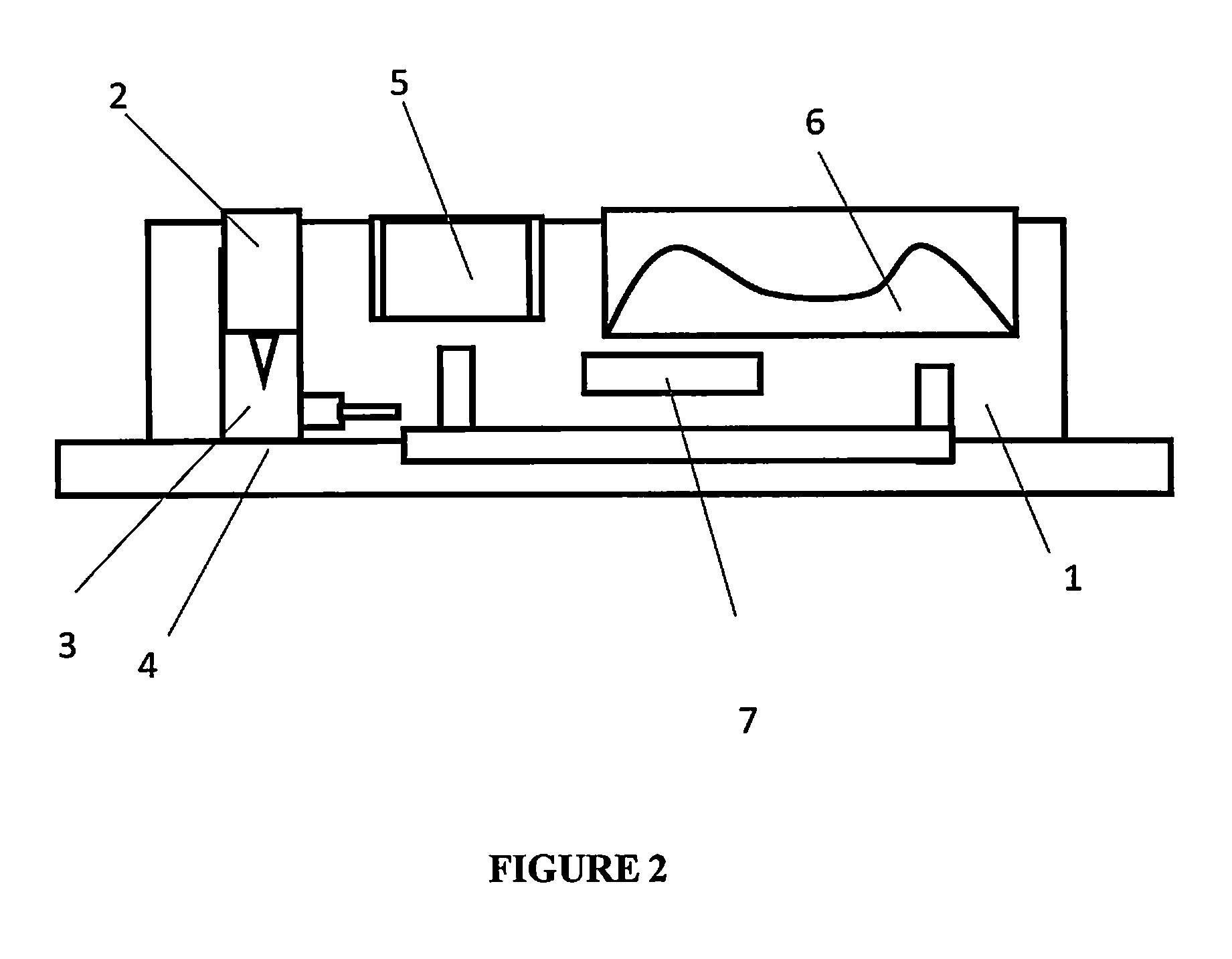
[0092]FIG. 2 shows a side view of an individual assay unit [1] within the disposable cartridge. Each individual assay unit has a piercing element [2] and a sampling chamber [3] for obtaining a biological sample at the sampling site [4]. The assay unit has a buffer reservoir [5] and a self-restoring chamber [6] for creating a vacuum and collecting waste solution. The assay unit also comprises an electrochemical sensor [7] for detecting the molecule of interest.

[0093]FIG. 3 shows the architecture for...

example 2

[0097]In use the apparatus is attached to the patient's body preferably via a skin adhesive, patient data is entered into the apparatus, the patient data communicated to the hospital electronic records and an authentication signal is received. On authentication, a spring-loaded skin puncturing needle is released to puncture the skin at a pre-programmed time and the blood sample is allowed to collect at the site of skin penetration until a minimum volume is generated. The blood sample is transported through microfluidic channels into a sensor chamber with an electrochemical-based cardiac marker immunosensor. Immunoassay reagents are automatically introduced into the sensor chamber and the excess blood sample and reagents are collected in a waste chamber. The cardiac marker concentration is measured via an electrochemical signal. The data is made available locally via a display on the apparatus and transmitted to the hospital electronic records. The apparatus uses algorithms which are...

example 3

[0101]FIG. 4 shows a top view schematic of an alternative embodiment of the disposable cartridge docked onto the reusable portion.

[0102]The sampling tubing [11] of the disposable cartridge is wrapped around the cam of the peristaltic pump [12] on the reusable portion [13] to complete the pump. This allows the expensive part of the pump to be reused while the tubing which is in contact with blood is disposable.

[0103]The tubing of the disposable cartridge [11] is in fluidic communication with a common fluidic line [14] within the cartridge as shown in FIG. 5. Along the common fluidic line are individual diaphragm / membrane valves [15] opening to biosensor modules [16]. At the other end of the common fluidic line is a fresh saline reservoir [17] and a waste reservoir [18] and their access are controlled by their respective miniature actuator controlled valves.

[0104]Each individual membrane valve separates biosensor fluidic entry from the common fluidic line. Each individual membrane val...


PUM


Abstract

The invention relates to systems, apparati, and methods for real-time diagnostics to detect and diagnose disease conditions in patients. In an embodiment, the apparatus is attached to a patient, takes samples of the patient's blood, allows real-time detection of markers in the patient's blood, and provides rapid diagnosis of the patient.

Description

FIELD OF THE INVENTION[0001]The invention relates to systems, apparati, and methods for real-time diagnostics to detect and diagnose disease conditions in patients.BACKGROUND OF THE INVENTION[0002]Every minute of every hour of every day, an American dies of heart attack. Myocardial Infarction (MI) or heart attack is one of the leading causes of death in the United States.[0003]Each year 8 MM patients in the US (15 MM worldwide) are admitted to emergency rooms (ER) for chest pain. For a very small fraction of these patients, diagnosis of MI is easily accomplished based on their ECG and appropriate treatment is provided to these patients in a timely manner. For the vast majority of the rest of these patients, the challenge is to rapidly triage them to determine which 10-15% need immediate intervention and which can be safely discharged.[0004]Early detection and diagnosis of an MI has long been pursued by doctors, clinicians and researchers alike in order to reduce mortality rates and ...

Claims


Application Information

Patent Timeline
IPC IPC(8): A61B5/15A61B5/1477A61B5/157A61B5/1455G06F19/00A61B5/151G16H10/40G16H40/67G16H50/20
CPCA61B5/150755G06F19/3418A61B5/15109A61B5/157A61B5/1477A61B5/150343A61B5/15087A61B5/1455A61B5/150969A61B5/6849A61B5/14503A61B5/14546A61B5/14865A61B2562/06A61B5/150022A61B5/150221A61B5/150229A61B5/150358A61B5/150809A61B5/150824A61B5/15117A61B5/1519A61B5/155G16H10/40A61B5/68335G16H40/67G16H50/20
Inventor BORIAH, VARUNCHUA, BEELEEDAMANI, RAMESH
Owner CARDIOCANARY
Why Eureka
Try Eureka