
Vacuum insulating glass (VIG) unit with metallic peripheral edge seal and/or methods of making the same

a technology of vacuum ionization glass and peripheral edge, which is applied in the direction of parallel plane units, doors/windows, building components, etc., can solve the problems of requiring a relatively long time to achieve an acceptable seal, unable to meet the requirements of high-temperature sealing processes discussed above, and not suitable for fabricating heat-sensitive components such as, for example, tempered vig units and encapsulating sensitive components

Active Publication Date: 2015-07-02
GUARDIAN GLASS LLC
View PDF4 Cites 25 Cited by
  • Summary
  • Abstract
  • Description
  • Claims
  • Application Information

AI Technical Summary

Benefits of technology

The patent text describes the use of glass frits or solders to create a vacuum or inert gas environment in glass substrates. The advantages of using these materials include a low melting point and versatility in bonding techniques. However, the challenge is to provide an edge seal that provides long-term hermeticity, mechanical strength, and low possible thermal pathways in harsh environments such as high operational temperatures, shocks, and vibrations.

Problems solved by technology

Gas tight packaging of the complex interiors of such assemblies has posed obstacles in the later stages of processing of such packages, such as, for example prior to pumping and tip fusing in the case of VIG window units, or last processing steps in the manufacture of OLED devices.
As a result, a relatively long period of time is required to achieve an acceptable seal.
Thus, high-temperature sealing processes discussed above (e.g., anodic bonding and glass frit bonding) are not suitable for fabricating heat-sensitive components such as, for example, tempered VIG units and encapsulating sensitive components, such as, for example, OLED devices.
In the case of tempered VIG units, the thermally tempered glass substrates of a VIG unit would rapidly lose temper strength in the high-temperature environment.
However, almost all lower melting point formulations of glass frit or solder contain some lead.
This may potentially become a drawback, as the U.S., EU, and Japan, for example, are severely limiting, if not forbidding, the use of lead in electronics manufacturing in the coming years.
In the last few years, frits or solders based on bismuth oxides have had some success in replacing lead based frits, however the melting temperature (Tg) of these types of frits is still typically above about 450 degrees C. As with lead based frits, these bismuth oxide based frits cannot be used for fabrication of temperature sensitive devices using conventional oven bulk heating processes.
However, widespread usage of these types of frits has been limited.
Moreover, although such glass fits are an improvement over conventional approaches, they sometimes still have difficulties meeting stringent thermo-mechanical requirement of a low temperature all-glass peripheral seal.
This is caused in part because low temperature glass solders usually are made of large ionic radii species do not readily diffuse into the glass surface at low processing temperatures and times.
For instance, the glazing industry subject materials to harsh environments with each extreme use posing its own challenges.
For example, in skylights, glazing systems are subjected to extreme temperatures (150 degrees C.) and shocks and vibration loading related to wind loads.
Indeed, ambient temperature near the VIG seal can reach in excess of 150 degrees C. with shock and vibration loading, and the ambient temperature in a building facade can be as high as 200 degrees C. Thus, it is challenging to provide an edge seal that provides long-term hermeticity, mechanical strength, and low possible thermal pathways.

Method used


Image

  • Vacuum insulating glass (VIG) unit with metallic peripheral edge seal and/or methods of making the same
  • Vacuum insulating glass (VIG) unit with metallic peripheral edge seal and/or methods of making the same
  • Vacuum insulating glass (VIG) unit with metallic peripheral edge seal and/or methods of making the same

Examples


Embodiment Construction

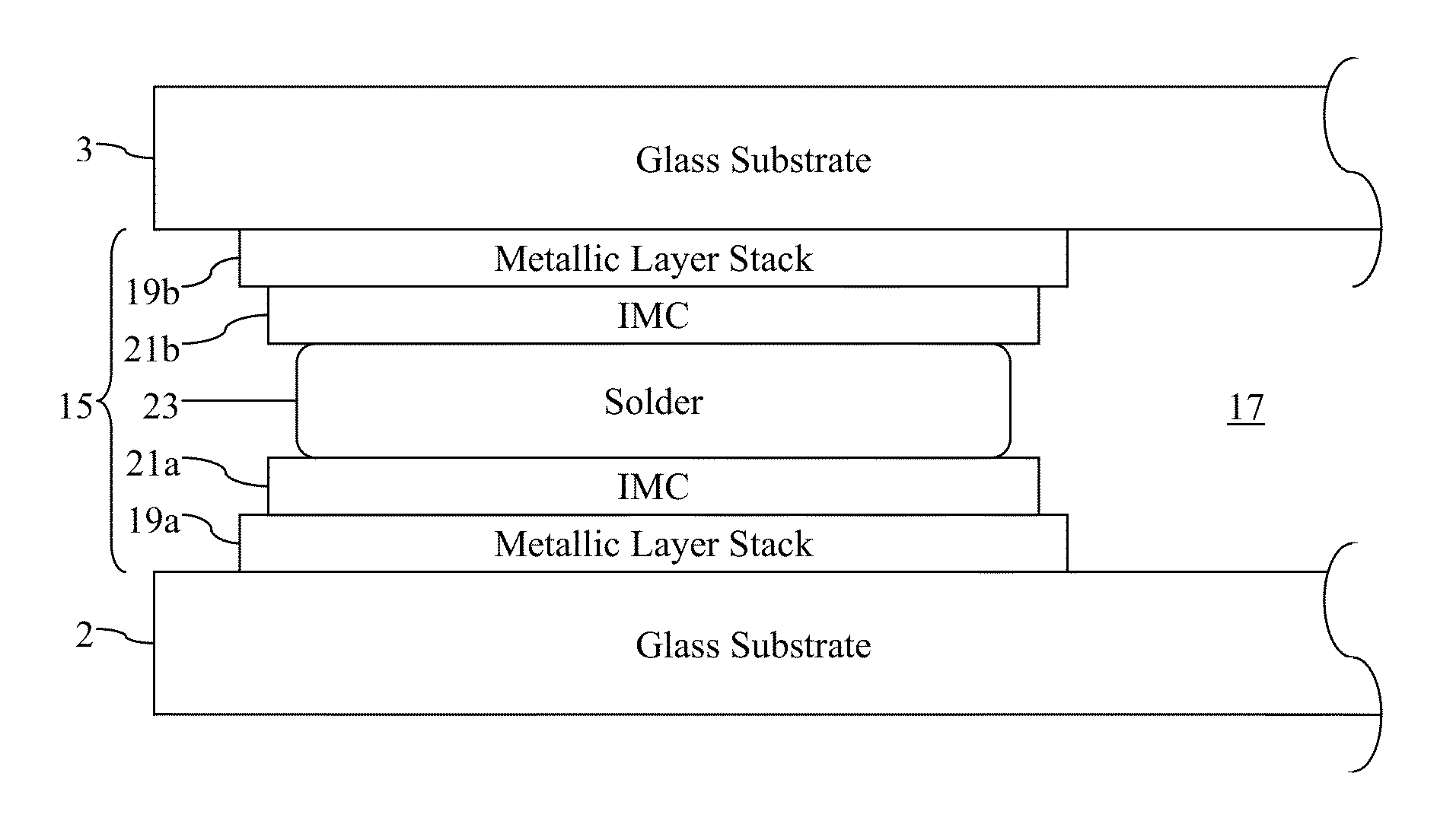
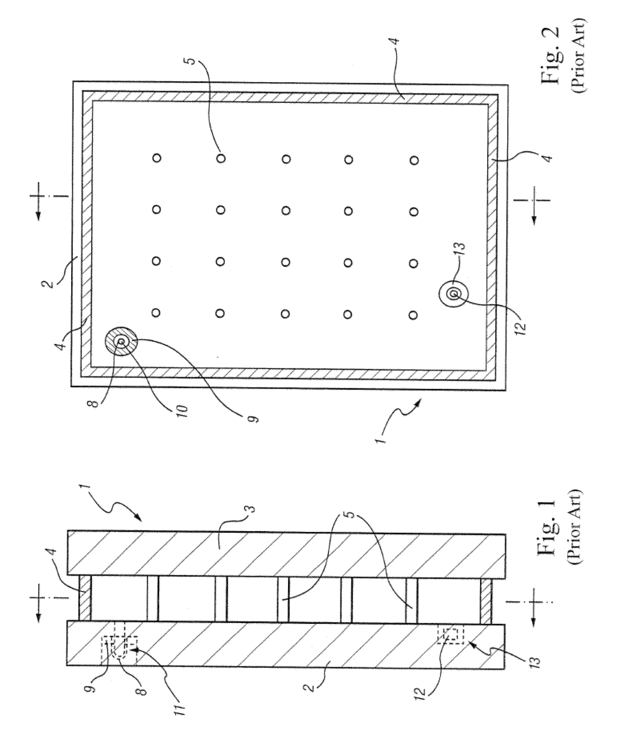
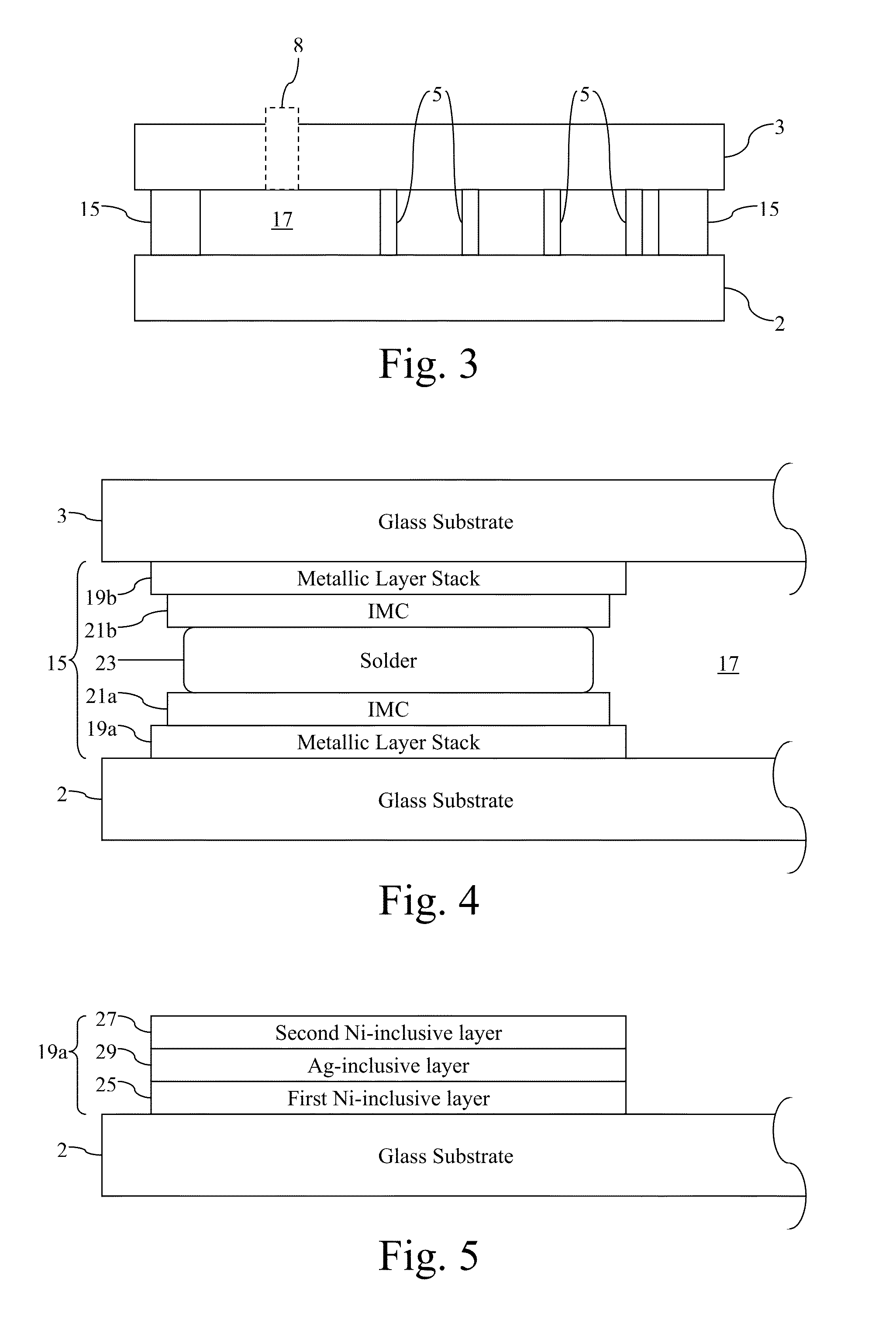
[0030]Certain example embodiments relate to a vacuum insulating glass (VIG) unit provided with a metal-inclusive peripheral edge hermetic seal, and / or methods of making the same. The primary material used in forming the edge seal is based on a metallic solder pre-form alloy that, when reactively reflowed, wets a metallic coating pre-coated on the glass substrates' perimeters. The use of these techniques advantageously permit low processing temperatures, e.g., through the careful selection of solder-coating combinations. This may in certain example embodiments advantageously allow thermally tempered glass to be used in VIG units without significantly sacrificing the temper strength of the glass during the fabrication process, permit sputtered soft low emissivity (low-E) coatings to be used, enable thin film getter materials to be provided, etc. In certain example embodiments, it advantageously becomes possible to form a vacuum without the use of a pump-out tube or the like.

[0031]More...


PUM

PropertyMeasurementUnit
thickaaaaaaaaaa
thickaaaaaaaaaa
pressureaaaaaaaaaa

Abstract

Certain example embodiments relate to vacuum insulating glass units having edge seals based on solder alloys that, when reactively reflowed, wet metallic coatings pre-coated on the glass substrates' perimeters, and / or associated methods. The alloys may be based on materials that form a seal at temperatures that will not de-temper glass and / or decompose a laminate, and / or remain hermetic and lack porous structures in their bulks. Example alloys may be based on inter-metallics of Sn and one or more additional materials selected from post-transition metals or metalloids; Zintl anions (e.g., In, Bi, etc.) from Group 13, 14, 15 or 16; and transition metals (e.g., Cu, Ag, Ni, etc.); and excludes Pb. Thin film coatings in certain example embodiments work with the solder material to form robust and durable hermetic interfaces. Because low temperatures are used, certain example embodiments can use compliant and visco-elastic spacer technology based on lamellar structures and / or the like.

Description

FIELD OF THE INVENTION[0001]Certain example embodiments of this invention relate to vacuum insulating glass (VIG or vacuum IG) units, and / or methods of making the same. More particularly, certain example embodiments of this invention relate to VIG units having edge seals based on metallic solder pre-form alloys that, when reactively reflowed, wet and bond with metallic coatings pre-coated on the glass substrates' perimeters, and / or associated methods.BACKGROUND AND SUMMARY OF EXAMPLE EMBODIMENTS OF THE INVENTION[0002]Hermetic sealing of glass substrates to create a vacuum or inert gas environment therebetween is typically made possible using barriers of usually glassy or metallic (e.g., eutectic) materials that are impermeable to ingress of gasses over a long time period, typically many orders of magnitude longer than the device operating lifetime. As will be understood, permeability typically involves two steps. These steps include dissolution and diffusion. Hermetic sealing helps ...

Claims


Application Information

Patent Timeline
Patent Type & Authority Applications(United States)
IPC IPC(8): E06B3/66E06B3/673E06B3/677
CPCE06B3/6775E06B3/6612E06B3/67334E06B3/67326E06B3/66357Y02A30/249Y02B80/22E06B3/66304
Inventor VEERASAMY, VIJAYEN S.BRACAMONTE, MARTIN D.
Owner GUARDIAN GLASS LLC
Learn More