Ozone abatement system for semiconductor manufacturing system

a technology of ozone abatement and manufacturing system, which is applied in ventilation systems, heating types, separation processes, etc., can solve the problems of requiring significant maintenance and cost, and affecting the quality of the environment, so as to reduce the ppmv of ozone, reduce the density of caustic materials, and reduce the density of ozon

Active Publication Date: 2015-07-16
IBM CORP
View PDF1 Cites 7 Cited by
  • Summary
  • Abstract
  • Description
  • Claims
  • Application Information

AI Technical Summary

Benefits of technology

[0010]At least one plate may be located in the reflective chamber to further aid in the laminar flow through the reflective chamber. As the plate is located in the reflective chamber the plate may be coated with a diffuse reflective material.
[0011]As the exhaust air may include caustic materials such as sulfuric acid, and to reduce the ppmv of the ozone, the system may be adding bleed air to the exhaust duct. By introducing bleed air the system reduces the density of the ozone in the air making the reflective chamber more effective. In addition, the bleed air lessens the density of the caustic materials in the exhaust air improving the life of the system.
[0012]To improve the performance of the system, a second reflective chamber may be added in series with the first reflective chamber. To ensure laminar flow a plurality of plates may be added to the first and second reflective chambers. The plates may be perforated with a plurality of holes. The plates may be at least the cross sectional area of the chamber cavity to ensure laminar flow. In addition, the reflective plates may be coated with a diffuse reflective material such as polytetrafluoroethylene.

Problems solved by technology

Many toxic materials are used in the fabrication process.
The role of ozone in the environment is more complicated.
However, it is harmful in the lower atmosphere since it is an irritant when breathed and is therefore an undesirable air pollution component.
One issue with the carbon filters is a result of the need to constantly change out the filters over time.
This requires significant maintenance and cost.

Method used


Image

  • Ozone abatement system for semiconductor manufacturing system
  • Ozone abatement system for semiconductor manufacturing system
  • Ozone abatement system for semiconductor manufacturing system

Examples


Embodiment Construction

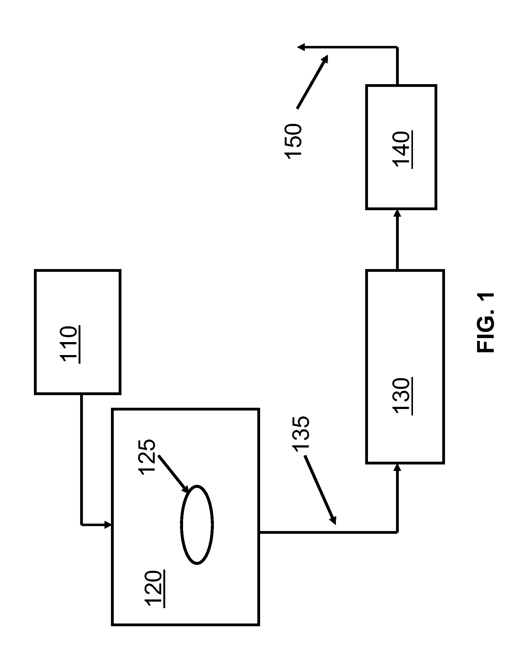
[0021]Referring to the drawings, FIG. 1 illustrates a schematic diagram of a conventional solution to the ozone abatement for the DNS single wafer processing tool. The ozone is generated with an ozone generator 110 which is provided to a process chamber 120. The ozone is mixed with sulfuric acid and off gases as the wafer 125 is processed. The off gas is exhausted through exhaust ducts 125 to a carbon filter 130. The exhaust ducts 135 may be stainless steel and coated with Halar to prevent damage from the sulfuric acid. The gas passing through the carbon filter 130 is then provided to an acid scrubber 140 to remove any remaining sulfuric acid. The gas is then exhausted through stack 150 into the atmosphere. The carbon filters 130 require maintenance as the ozone and sulfuric acid is absorbed by the filters. This requires periodic replacement of the filter and disposal of the used filters. This may be costly and involve significant manpower. The inventor proposes a solution to this e...


PUM


Abstract

An apparatus and method for abating ozone and reducing sulfuric acid from an exhaust stream. In a semiconductor manufacturing plant the processing of wafers involves the cleaning and etching of wafers, the resultant processing may produce gasses which must be abated. The apparatus and method utilizes UV light in high doses to convert ozone (O3) to oxygen (O2). By ensuring laminar flow through the UV light chambers, the efficiency of the system is sufficient to allow for the remaining impurities in the exhaust air to be removed through the use of an RTO.

Description

FIELD OF THE INVENTION[0001]The present invention relates to methodologies and an apparatus for the abatement of ozone produced during the processing of semiconductor wafers.BACKGROUND[0002]Semiconductor device fabrication involves various processing steps which may fall into four general categories: deposition, removal, patterning, and modification of electrical properties. Deposition is any process that grows, coats, or otherwise transfers a material onto the wafer. Available technologies include physical vapor deposition (PVD), chemical vapor deposition (CVD), electrochemical deposition (ECD), molecular beam epitaxy (MBE) and more recently, atomic layer deposition (ALD) among others. Removal is any process that removes material from the wafer; examples include etch processes (either wet or dry) and chemical-mechanical planarization (CMP). Patterning is the shaping or altering of deposited materials, and is generally referred to as lithography. For example, in conventional lithogr...

Claims


Application Information

Patent Timeline
Patent Type & Authority Applications(United States)
IPC IPC(8): B01D53/00F15D1/00B01D53/66F24F7/06
CPCB01D53/007F24F7/06B01D2259/804B01D53/66F15D1/003F23G7/068B01D2258/0216Y10T137/206Y02A50/20
Inventor PEPE, EDWARD L.
Owner IBM CORP
Why Eureka
Try Eureka