
Cfrp resistive sheet heating

Inactive Publication Date: 2015-07-23
WOBBEN PROPERTIES GMBH
View PDF8 Cites 20 Cited by
  • Summary
  • Abstract
  • Description
  • Claims
  • Application Information

AI Technical Summary

Benefits of technology

This patent proposes a way to increase the heating performance of a heating wire by changing its amplitude and wavelength while keeping the distance between the starting and end points the same. The surge protector is also designed to prevent damage to surrounding elements in case of a lightning strike. The proposed solution includes an encapsulated surge protector that can be easily installed and removed from the rotor blade. Overall, this technology prevents explosions and damage to the rotor blade caused by lightning strikes.

Problems solved by technology

This has the disadvantage that the de-icing effect is already significantly reduced in the place where most icing occurs, i.e., at the tip of the blade.

Method used


Image

  • Cfrp resistive sheet heating
  • Cfrp resistive sheet heating
  • Cfrp resistive sheet heating

Examples


Embodiment Construction

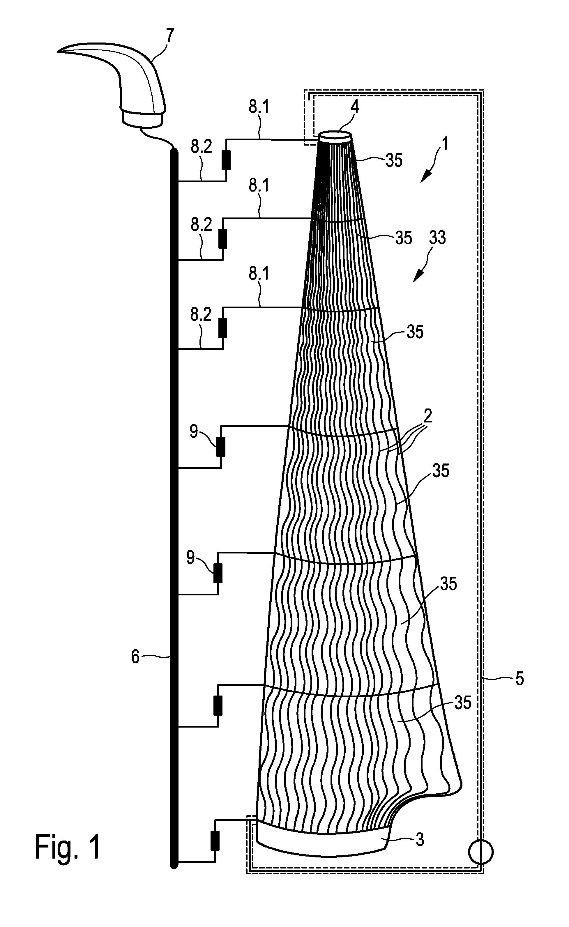
[0055]FIG. 1 shows a schematic view of a rotor blade 1 according to one embodiment of the invention, which, along its longitudinal axis, is interspersed with carbon fiber strings 2. These are integrated in the form of a sine wave oscillating in parallel to the blade surface. The amplitude of the sine wave decreases from the blade root 3 to the blade tip 4. Since the circumference of the blade decreases towards the blade tip, there, the strings are closer together than at the blade root. Thus, the energy input increases relative to the blade surface. This is an advantage, since, during operation, the blade tip moves at a higher true velocity than the blade root, and, therefore, is more prone to icing. The electric circuit is closed by a wire 5, which is only schematically indicated in this figure.

[0056]Thus, the specific areal heating performance is necessarily increased due to the closer arrangement of the heating wires, namely the carbon fiber strings 2. That is, the area of the ro...


PUM

PropertyMeasurementUnit
Lengthaaaaaaaaaa
Electrical conductivityaaaaaaaaaa
Poweraaaaaaaaaa

Abstract

The invention relates to a rotor blade of a wind power installation comprising a heating device for heating the rotor blade, arranged in the rotor blade in the area of its rotor blade surface, wherein the heating device has electrically conductive heating wires, and the heating wires run in a sinusoidal, wave-like and / or zigzag-shaped way, with an amplitude, defining a sinusoidal amplitude, wave height or respectively spike height, and a wavelength defining a period length, wavelength or respectively a distance between spikes, wherein the amplitude and / or wavelength varies along the heating wires in order to be able to adjust the specific areal heating performance of the heating device for each section.

Description

BACKGROUND[0001]1. Technical Field[0002]The invention relates to a heatable rotor blade of a wind power installation. The invention relates further to a method for heating a rotor blade of a wind power installation and the invention concerns a wind power installation. In addition, the present invention relates to a surge protector to be set up within a rotor blade and the invention concerns a heating device for heating a rotor blade. Furthermore, the invention relates to a method for designing a heating device.[0003]2. Description of the Related Art[0004]At temperatures below 0° C. or slightly above, icing can occur on the rotor blades of wind power installations. According to prior art, this problem is countered by rotor blade heating systems. A process for de-icing a rotor blade of a wind power installation is known from EP 0842360. This process is based on the object of finding a process for preventing the disadvantages resulting from the icing of the rotor blades that is simple ...

Claims


Application Information

Patent Timeline
IPC IPC(8): F03D11/00H01T4/08H01T4/02F01D5/14
CPCF03D11/0025H01T4/02H01T4/08F01D5/147Y02E10/72F03D80/40F03D80/30Y10T29/49083F03D1/06F03D80/00
Inventor CLEMENS, CHRISTIAN
Owner WOBBEN PROPERTIES GMBH
Learn More