
Ceramic circuit board of laser plate copper and manufacturing method thereof

a technology of ceramic circuit board and laser plate copper, which is applied in the direction of printed circuit aspects, specific circuit substances, electrical equipment, etc., can solve the problems of adversely increasing manufacturing costs, affecting the quality of laser plate copper, and the equipment cost through the process is in the midrange, so as to improve the yield rate, improve the adhesive and plating quality, and improve the effect of durability and productivity

Inactive Publication Date: 2015-07-23
RHEMA TECH & TRADING COMPANY
View PDF0 Cites 14 Cited by
  • Summary
  • Abstract
  • Description
  • Claims
  • Application Information

AI Technical Summary

Benefits of technology

The present disclosure is about a ceramic circuit board and a manufacturing method thereof. The invention focuses on improving the quality of adhesion and plating between the ceramic substrate and the metal layer, which increases the yield rate and durability of the ceramic circuit board. The technical effect of this invention is to enhance the performance of laser plate copper ceramic circuit boards.

Problems solved by technology

In the LTCC process, the line-width resolution is about 150 μm˜300 μm and the circuit accuracy level is 10%, but the circuit board made by the LTCC process cannot be applied to flip-chip packaging and the equipment cost through the process is in the midrange.
The LTCC process has a long turnaround time in making sample circuits and changing design order, which adversely increases the manufacturing cost, and three-dimensional circuits can not be made through the LTCC process.
Additionally, the ceramic substrate used in the process is usually included with 30%˜50% glass material to lower the sintering temperature during the process, making the thermal conductivity of the substrate to be about 2˜3 W / m° C., thus limiting the scope of the applications.
However, the equipment cost through the process is relatively expensive, and the DPC process also has a long turnaround time in making sample circuits and changing design order (typically for 1˜2 weeks), making the manufacturing cost expensive, and three-dimensional circuits cannot be made through the DPC process.
However, in the manufacture using conventional laser engraving processes, the plating capability of the metal trace may not be good enough to attach securely to the surface of the ceramic circuit board and result in pilling effect.
Moreover, the surface-mounted device (SMD) process during the manufacture of ceramic circuit board requires a high-temperature (at 260° C.˜290° C.) operation environment, which is also prone to causing the pilling effect on the metal trace.
High percentage of pilling on the surface of the ceramic substrate further reduces the yield rate, durability, and productivity of the products.

Method used


Image

  • Ceramic circuit board of laser plate copper and manufacturing method thereof
  • Ceramic circuit board of laser plate copper and manufacturing method thereof
  • Ceramic circuit board of laser plate copper and manufacturing method thereof

Examples


Embodiment Construction

[0037]In order to further understand the present disclosure, preferred embodiments are to be described such that variations and alterations thereto are readily apparent to a person skilled in the art. However, it will be realized that the scope of this disclosure is not confined or restricted to the details of the embodiments described below. Identical reference numerals always designate the same elements throughout all the figures of the drawing.

[0038]The present disclosure provides a ceramic circuit board of laser plate copper (LPC) comprising a ceramic substrate and a metal layer. The surface of the ceramic substrate includes a circuit pattern composed of multiple groove structures of laser plate copper, in which the amount of the aluminum constituent in the ceramic substrate ranges from 35 wt % to 55 wt %. The metal layer is plated on the groove structures to form the conductive loop defined by the circuit pattern.

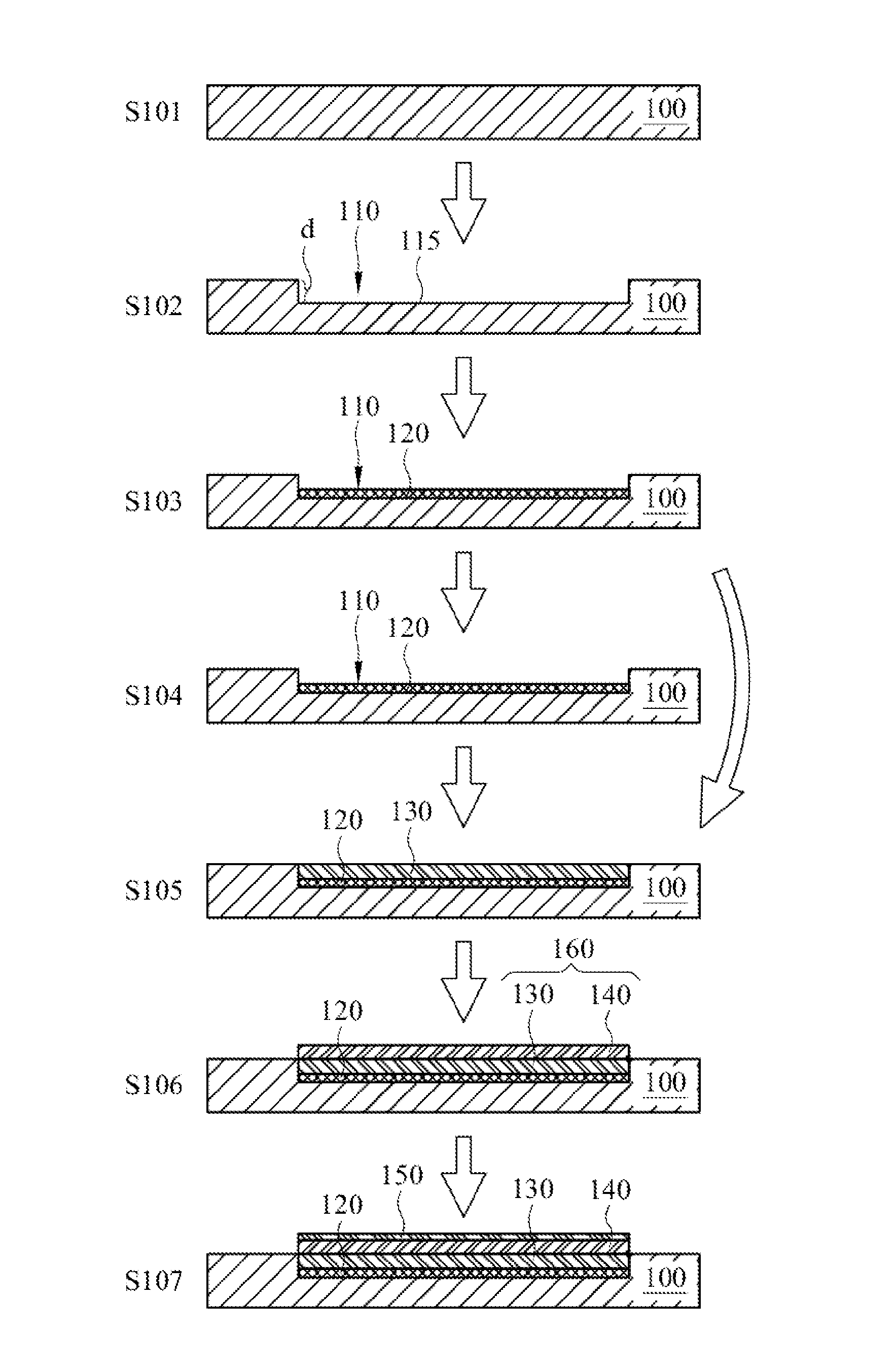
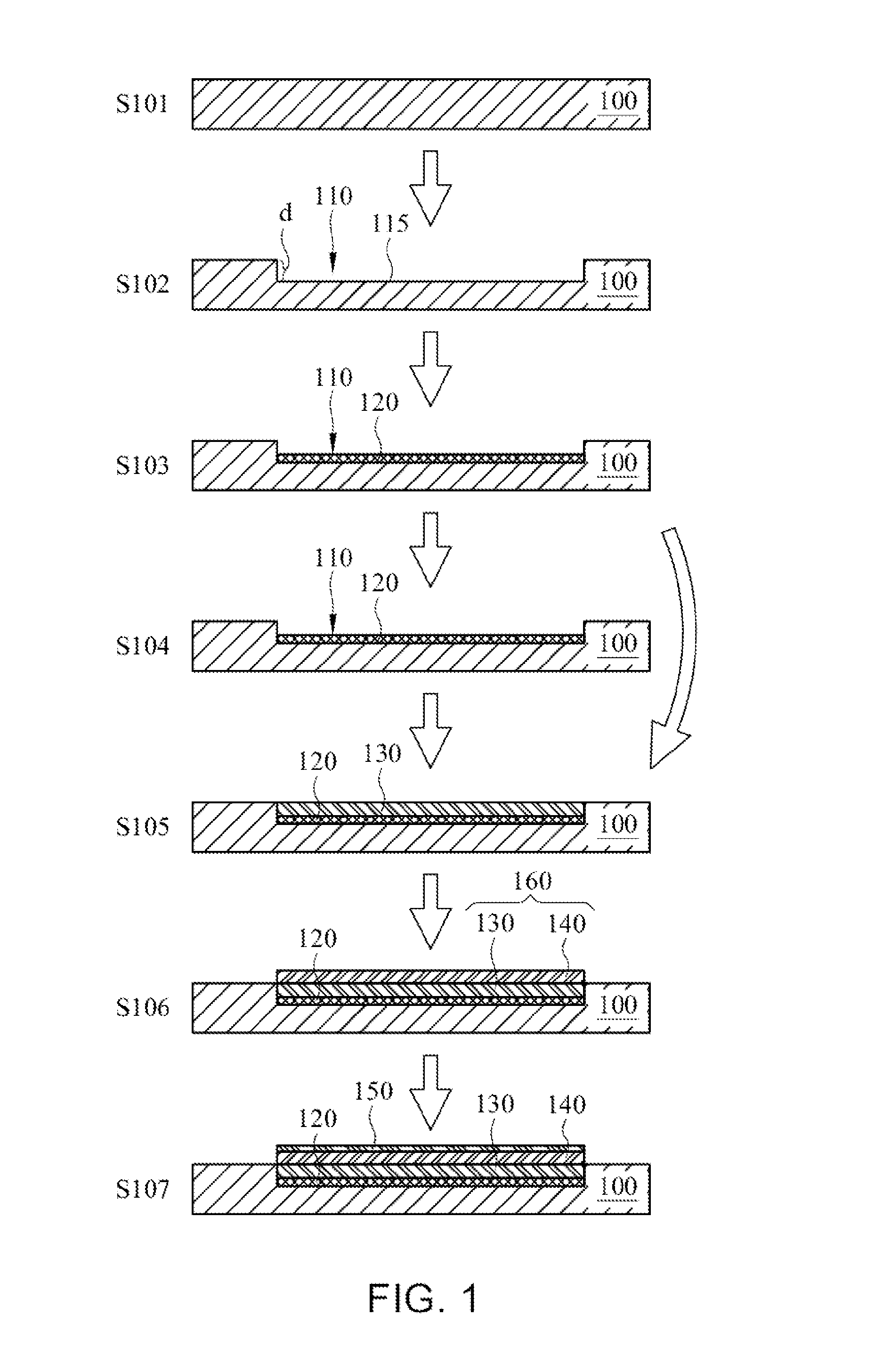
[0039]FIG. 1 shows a schematic view of a manufacturing method mak...


PUM

PropertyMeasurementUnit
Temperatureaaaaaaaaaa
Lengthaaaaaaaaaa

Abstract

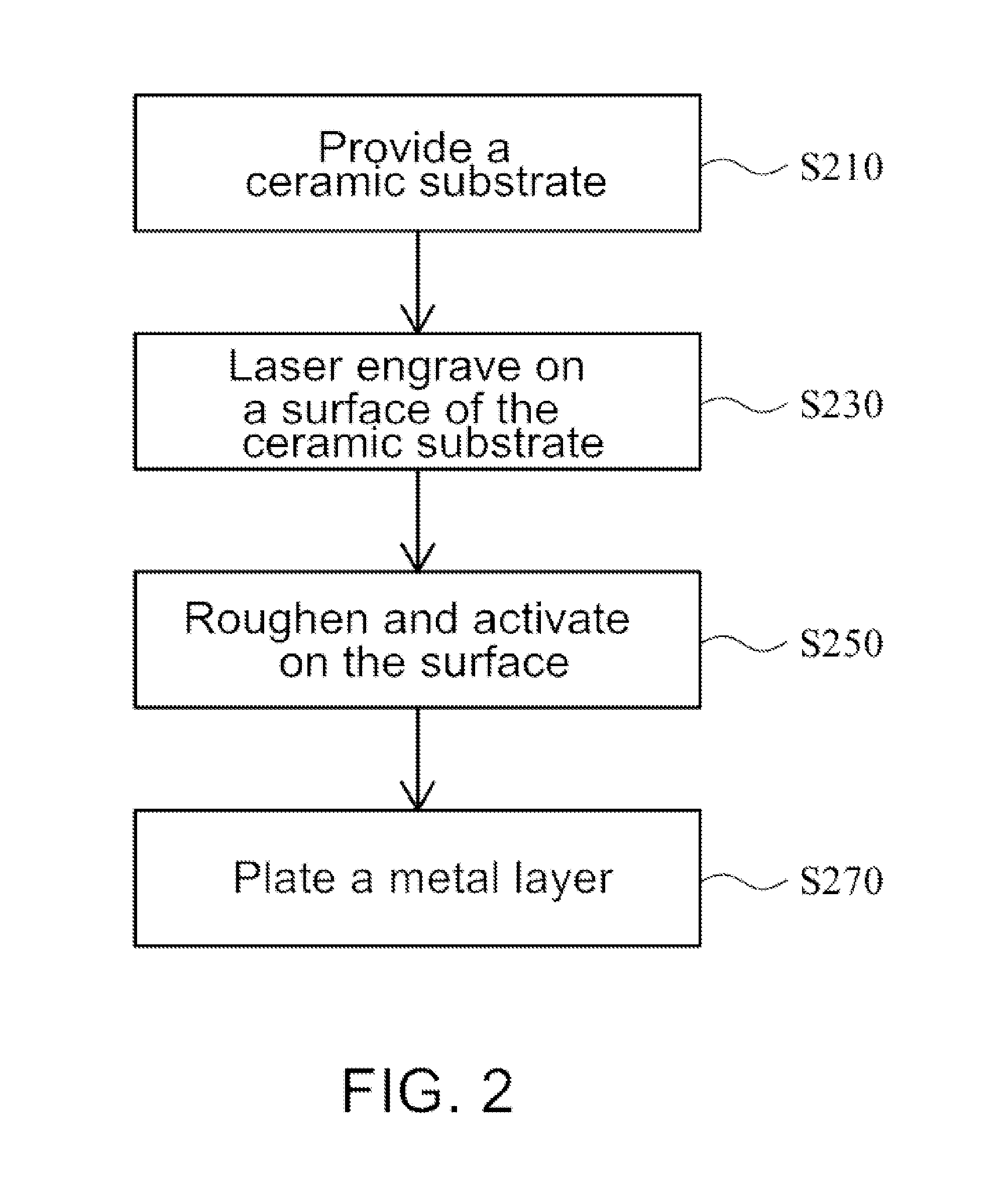
A ceramic circuit board of laser plate copper and manufacturing method thereof is provided. The method includes: providing a ceramic substrate; laser engraving, on a surface of the ceramic substrate, so as to form a circuit pattern of a plurality of groove structures; roughening and activating, on the surface of the ceramic substrate, by washing the surface of the ceramic substrate with a roughening and activating solution; and plating a metal layer, on the groove structures, so as to form a conductive loop defined by the circuit pattern.

Description

CROSS-REFERENCE TO RELATED APPLICATIONS[0001]This non-provisional application claims priority under 35 U.S.C. §119(a) on Taiwan Patent Application No. 103101966 filed Jan. 20, 2014, the contents of which are incorporated herein by reference in its entirety.BACKGROUND[0002]1. Technical Field[0003]The present disclosure relates to a ceramic circuit board and, more particularly, to a ceramic circuit board of laser plate copper (LPC) and manufacturing method thereof[0004]2. Description of Related Art[0005]There is a need to improve the manufacturing process of a ceramic circuit board in the art. The ceramic circuit board is suitably applied to high power devices, such as high-power power module products, high-power light-emitting diode (LED) illumination products, and high-power high-frequency microwave products. The ceramic circuit board adopts a ceramic substrate with efficient heat dissipation and high-current load capability, which enables it to withstand under harsh work environmen...

Claims


Application Information

Patent Timeline
IPC IPC(8): H05K1/03H05K1/09H05K1/02H05K3/10
CPCH05K1/0306H05K3/107H05K1/09H05K2201/09036H05K2203/107H05K2203/12H05K2201/10106H05K1/0284H05K3/0029H05K3/18H05K3/381H05K2201/0338Y10T29/49155
Inventor WU, KU CHOU
Owner RHEMA TECH & TRADING COMPANY
Learn More