Reactor assembly and method for polymerization of olefins

a technology of olefin and assembly method, which is applied in the direction of chemical/physical/physical-chemical processes, chemical apparatus and processes, chemical/physical processes, etc., can solve the problems of unfavorable material separation, increased bubble size, and material unfavorable dissolution,

Active Publication Date: 2015-08-06
BOREALIS AG
View PDF2 Cites 2 Cited by
  • Summary
  • Abstract
  • Description
  • Claims
  • Application Information

AI Technical Summary

Benefits of technology

[0012]The present invention is based on the finding that these problems can be overcome by a fluidized bed reactor assembly allowing for variat

Problems solved by technology

Yet another fundamental problem with traditional fluidized bed reactors are the limitations as to the cooling capacity and entrainment due to the formation of huge bubbles.
Increasing the bed level in conventional fluidized bed reactors for increasing the space-time yield leads to an increase of the bubble size and to an unwanted entrainment of material from the reactor.
In conventional reactors there are no means for breaking up the bubbles.
However, the fluidized bed reactors and the dual reactor assemblies comprising a fluidized bed reactor described in the prior art still have several disadvantages.
A first problem concerns the plugging of the underside of the distribution plates due to entrainment of fines carried over with the circulation gas.
This effect lowers operational stability and stability of the quality of the polymer.
However, a relatively low fluidization gas velocity limits the production rate and can lead to the formation of sheets, chunks and lumps in the production of polyolefins.
However, disengagement zones again limit the production rate of a gas phase reactor of fixed size, as there is the need

Method used


Image

  • Reactor assembly and method for polymerization of olefins
  • Reactor assembly and method for polymerization of olefins
  • Reactor assembly and method for polymerization of olefins

Examples


example 1

Comparative

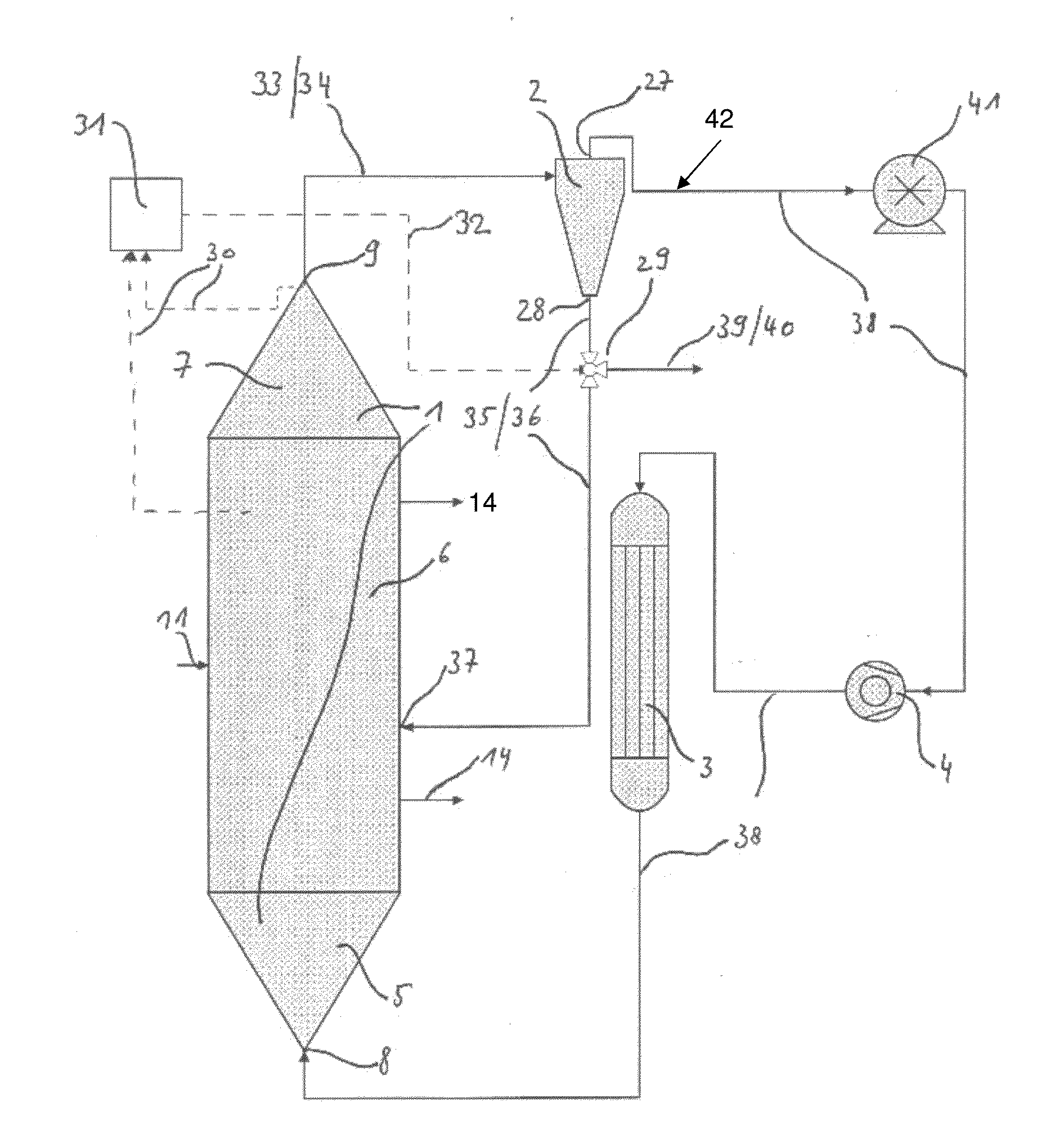
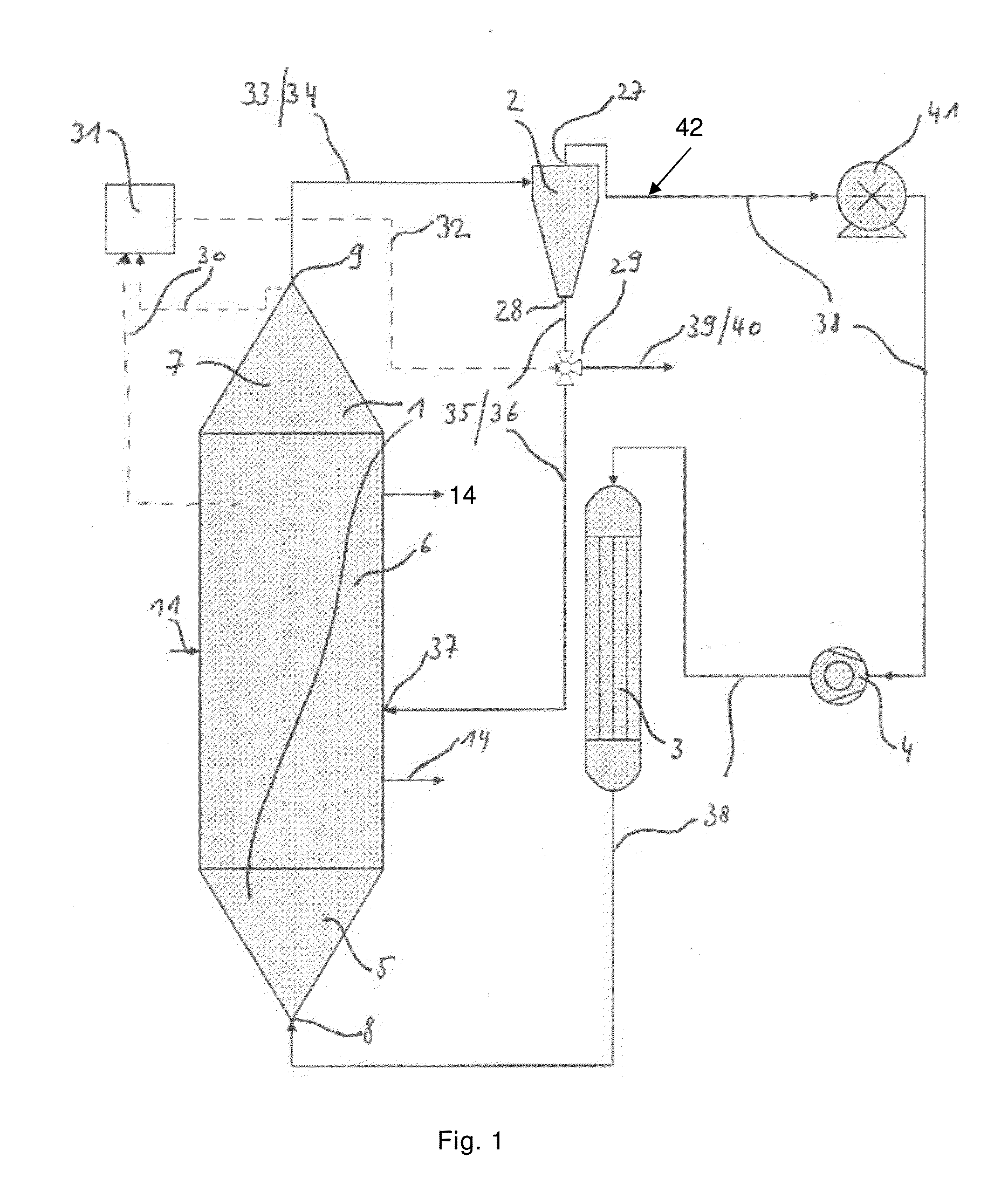
[0325]The invention was exemplified with a reactor made of steel having the following dimensions:

[0326]Height of the bottom zone: 1680 mm

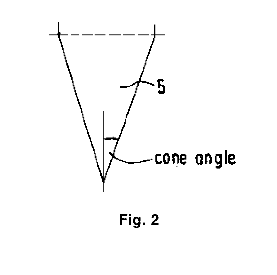
[0327]Diameter at the bottom of the bottom zone: 175 mm

[0328]Height of the middle zone: 2050 mm

[0329]Height of the upper zone: 670 mm

[0330]Diameter of the middle zone: 770 mm

[0331]The operation of the reactor was stable and without problems.

[0332]The reactor described above was used for copolymerization of ethylene and 1-butene at a temperature of 80° C. and a pressure of 20 bar. The height of the fluidized bed, calculated from the bottom of the middle zone was 2100 mm.

[0333]Ethylene homopolymer (MFR2=300 g / 10 min, density 974 kg / m3) produced in a loop reactor and still containing the active catalyst which one dispersed therein was introduced into the above reactor via an inlet located in the bottom zone at a rate of 40 kg / h. Ethylene, hydrogen and 1-butene were continuously introduced into the circulation gas line so that the ethylene c...

example 2

Inventive

[0335]Procedure of Example 1 was repeated. Then, the solid recycling stream withdrawn at the bottom outlet from the cyclone was returned to the fluidized bed reactor. When the reactor was operated in this way the bed level increased in one hour to 2300 mm. At the same time the solids content in the fluidization gas stream increased to 0.4% by weight and 19.2 kg / h of polymer were transported by the fluidization gas stream to the cyclone. The flow of polymer captured from the solid recycling stream at the bottom outlet of the cyclone was 18.9 kg / h and 0.3 kg / h remained in the in the overhead stream of the cyclone.

[0336]The polymer withdrawal rate from the bed was then lowered to 61 kg / h. After one hour of operation the flows were changed so that the solid recycling stream (36) was 11.5 kg / h, the stream to downstream process stages (40) was 7.5 kg / h and polymer withdrawal stream (14) from the reactor was 72 kg / h. A stable operation was achieved with no problem of fouling in th...


PUM

PropertyMeasurementUnit
Fractionaaaaaaaaaa
Speedaaaaaaaaaa
Velocityaaaaaaaaaa

Abstract

Reactor assembly for the production of polymers including a fluidized bed reactor and method for operating the reactor assembly.

Description

[0001]The invention relates to a fluidized-bed reactor assembly for the polymerisation of olefinic monomer(s), and to multi reactor assemblies comprising at least one fluidized bed reactor. Furthermore, the invention relates to a method of operating and use of such a fluidized-bed reactor assembly.BACKGROUND[0002]Gas phase reactors are commonly used for the polymerization of olefins such as ethylene and propylene as they allow relative high flexibility in polymer design and the use of various catalyst systems. A common gas phase reactor variant is the fluidized bed reactor. In polyolefin production, olefins are polymerized in the presence of a polymerization catalyst in an upwards moving gas stream. The fluidization gas is removed from the top of the reactor, cooled in a cooler, typically a heat exchanger, re-pressured and fed back into the bottom part of the reactor. The reactor typically contains a fluidized bed comprising the growing polymer particles containing the active cataly...

Claims


Application Information

Patent Timeline
IPC IPC(8): C08F210/16B01J8/24
CPCB01J8/1827C08F210/16B01J8/388B01J19/2465B01J8/0055B01J8/006B01J2208/00256B01J2208/00274B01J2208/00292B01J2208/00672B01J2219/00247B01J2219/00254B01J8/24B01J2208/00752B01J2208/00761B01J2208/00893B01J2208/00938B01J8/1872
Inventor KANELLOPOULOS, VASILEIOSAL-HAJ ALI, MOHAMMAD
Owner BOREALIS AG
Why Eureka
Try Eureka