Method to optimize a light coupling waveguide

Active Publication Date: 2015-08-06
CSEM CENT SUISSE DELECTRONIQUE & DE MICROTECHNIQUE SA RECH & DEV
View PDF7 Cites 35 Cited by
  • Summary
  • Abstract
  • Description
  • Claims
  • Application Information

AI Technical Summary

Benefits of technology

[0008]It is therefore an object of the present invention to couple light into a multimode waveguide, e.g. a bulk transparent material, with a very high efficiency, while imposing some constraints on the waveguide shape to be compatible with mass production manufacturing techniques. The applicant has identified that efficient coupling of the incident beam into the multimode waveguide is achieved if the wavefront of the coupled light in the waveguide is able to propagate along a specific diffraction order, different than the zero order. In the present invention the multimode waveguide consists of a transparent optical foil or sheet, such as a glass plate, a polymer foil or the like, which at one side or both sides of the surface has an optical coupling structure which couples an incident light beam into the waveguide. The coupling structure is periodic and therefore produces diffraction of the incident light beam. Efficient coupling into the waveguide is achieved if only the first and/or the minus first diffraction order is coupled into the waveguide. Alternatively also the second and minus second

Problems solved by technology

It is generally assumed that grating coupling to multimode waveguides has an inherently poor efficiency as remarked by Destouches et. al.
Even in publications which achieve high coupling efficiency for reflective gratings, Janyce Franc et. al. state that “It is usually believed that grating coupling to a multimode waveguide has extremely low efficiency.
Only a few alternative solutions describing a multimodal waveguide for coupling light have been investigated as the materials that are used are expensive and as their manipulation is complex.
This results in a structure that is difficult and expensive to mass-produce; standard surface embossing cannot produce it.
The devices disclosed in these documents are not suitable for applications requiring bulk waveguides with thicknesses typical

Method used


Image

  • Method to optimize a light coupling waveguide
  • Method to optimize a light coupling waveguide
  • Method to optimize a light coupling waveguide

Examples


Embodiment Construction

[0041]Unless specified otherwise, every example disclosed in this document is using a waveguide in an ambient environment composed of air, i.e. with a refractive index n1=1. Also, unless specified otherwise, the incident light beam that hits the waveguide is polarized, with its polarization parallel to the structures of the grating, in other words, a TE polarized light.

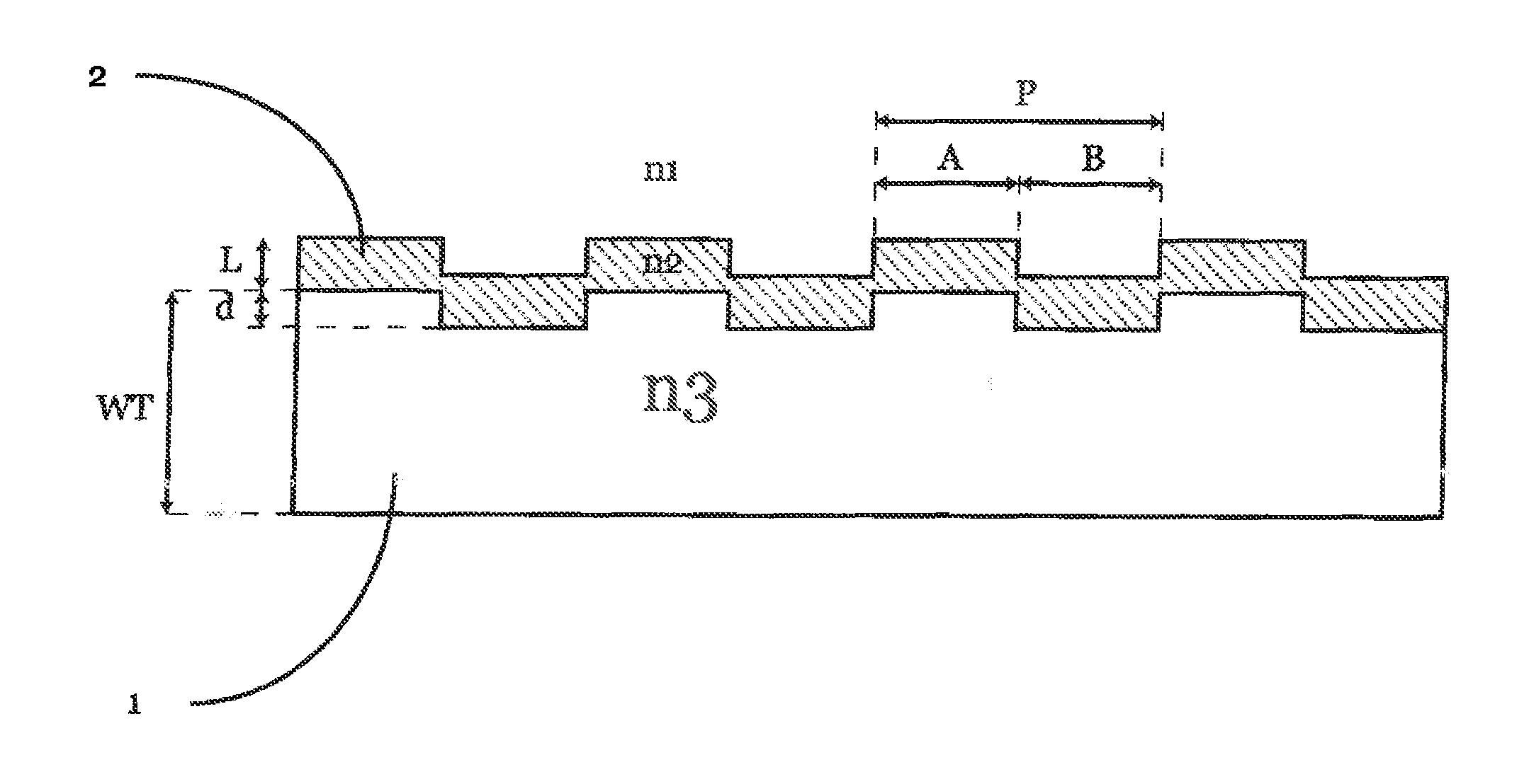
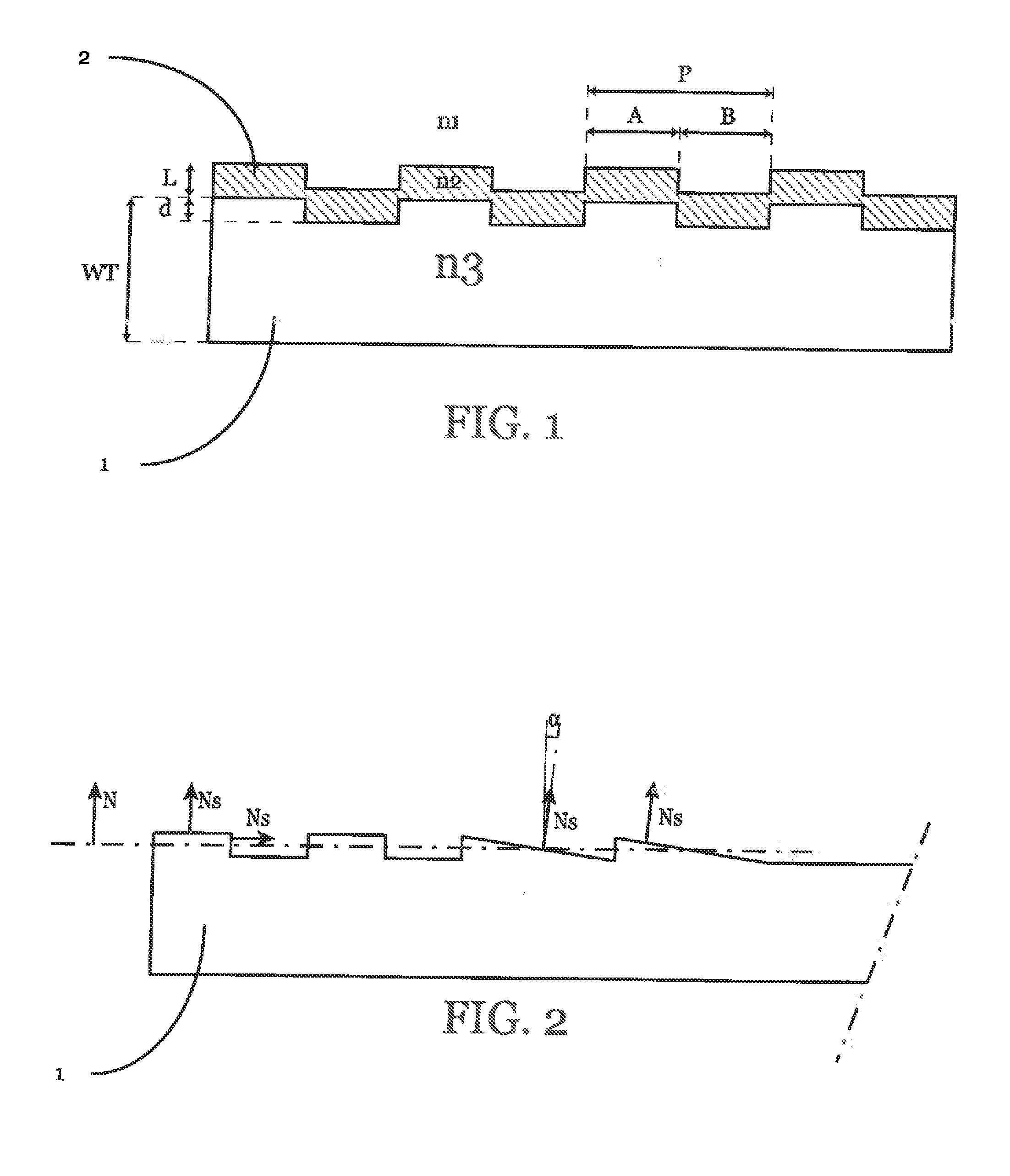
[0042]The invention concerns a method for constructing a light coupling system wherein a grating comprising a repetition of patterns is manufactured on the surface of a multimode waveguide. Engraving, or hot embossing, or injection molding, or any other suitable method can be used to manufacture the grating. This method comprises a step of choosing a first set of parameters comprising:[0043]wavelength distribution of the incident light to be transmitted by the waveguide,[0044]polarized or unpolarized nature of said incident light,[0045]incident angle standard deviation (Sθ) of the incident light with respect to the wa...


PUM


Abstract

The present invention concerns a method for constructing a light coupling system wherein a grating is manufactured on the surface of a multimode waveguide and defines the entrance of the waveguide for an incident light beam, said grating comprising a repetition of patterns. The grating is defined by a set of parameters comprising: •grating period (P), separating two adjacent patterns, •grating depth (d) between the highest and the lowest point of the pattern, •incident angle mean value (θ) of the incident light with respect to the waveguide. The method comprises a step of optimization of the set of parameters to obtain an optimized second set of parameters, in order to obtain a transmission efficiency (Ce) of the incident light into said waveguide for the first or the second diffractive order exceeding 35% for unpolarized light, or exceeding 50% for polarized light, at a given wavelength of the incident light.

Description

TECHNICAL FIELD[0001]The present invention concerns a method to devise a multimodal waveguide comprising a periodic diffractive grating. The method aims to optimize the coupling efficiency of an incident light beam coupled into such a waveguide. The invention also concerns the device obtained by the disclosed method.STATE OF THE ART[0002]Most of the existing solutions for guiding light have been focused so far on single mode waveguides. Indeed, such a waveguide makes the light transmission easier as only the mode of order zero is transmitted into the waveguide in a straight path. The coupling efficiency corresponds to the efficiency of optical power transfer between two optical components. For example, the transfer may take place between an active component, such as a Light Emitting Diode (LED), and a passive component, such as an optical fiber, or between two passive components such as two optical fibers. Coupling efficiency is usually expressed as the ratio, converted to percent, ...

Claims


Application Information

Patent Timeline
IPC IPC(8): G02B6/02B29D11/00
CPCG02B6/29397G02B6/34G02B6/2793G02B6/29323G02B2006/02166B29D11/00692B29L2011/0075G02B6/02085G02B6/02123G02B6/29329
Inventor SQALLI, OMARPIRES, DAVIDBASSET, GUILLAUMESTALDER, MARTIN
Owner CSEM CENT SUISSE DELECTRONIQUE & DE MICROTECHNIQUE SA RECH & DEV
Why Eureka
Try Eureka