Sealant for LED device, LED device, and method for producing LED device

a technology of led devices and sealants, applied in the direction of chemistry apparatus and processes, inks, other chemical processes, etc., can solve the problems of difficult to obtain sufficient outcoupling efficiency, reflection efficiency is reduced, and the outcoupling efficiency is markedly reduced, etc., to achieve excellent adhesion, not easily cracked, and high sulfide gas resistance

Inactive Publication Date: 2015-08-06
KONICA MINOLTA INC
View PDF5 Cites 17 Cited by
  • Summary
  • Abstract
  • Description
  • Claims
  • Application Information

AI Technical Summary

Benefits of technology

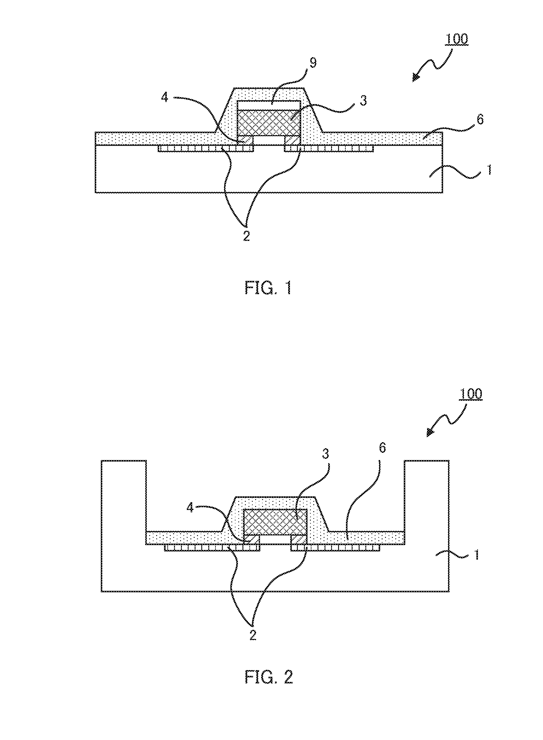
[0025]The cured film of the sealant for an LED device of the present invention has excellent adhesion with respect to the LED element (for example, a metallic reflector or a package) and also has a high sulfide gas resistance. Further, the sealant for an LED device of the present invention is not much contracted during curing, and, thus, the cured film is not easily cracked. Therefore, the first LED device including the cured film of the sealant has high sulfide gas resistance as well as excellent adhesion and outcoupling efficiency.
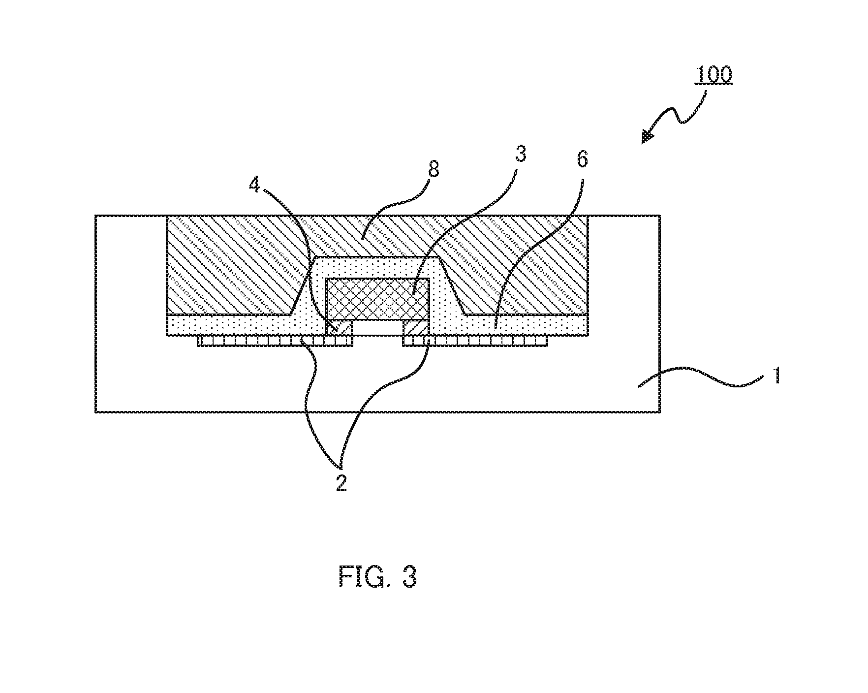
[0026]The light transmissive layer of the second LED device of the present invention has very high adhesion to the wavelength conversion layer and also has excellent light transmissivity. Further, the light transmissive layer is not easily cracked, and, thus, a gas barrier property is less likely to decrease as time passes. Therefore, the LED device of the present invention has a high sulfide gas resistance over a long period of time.
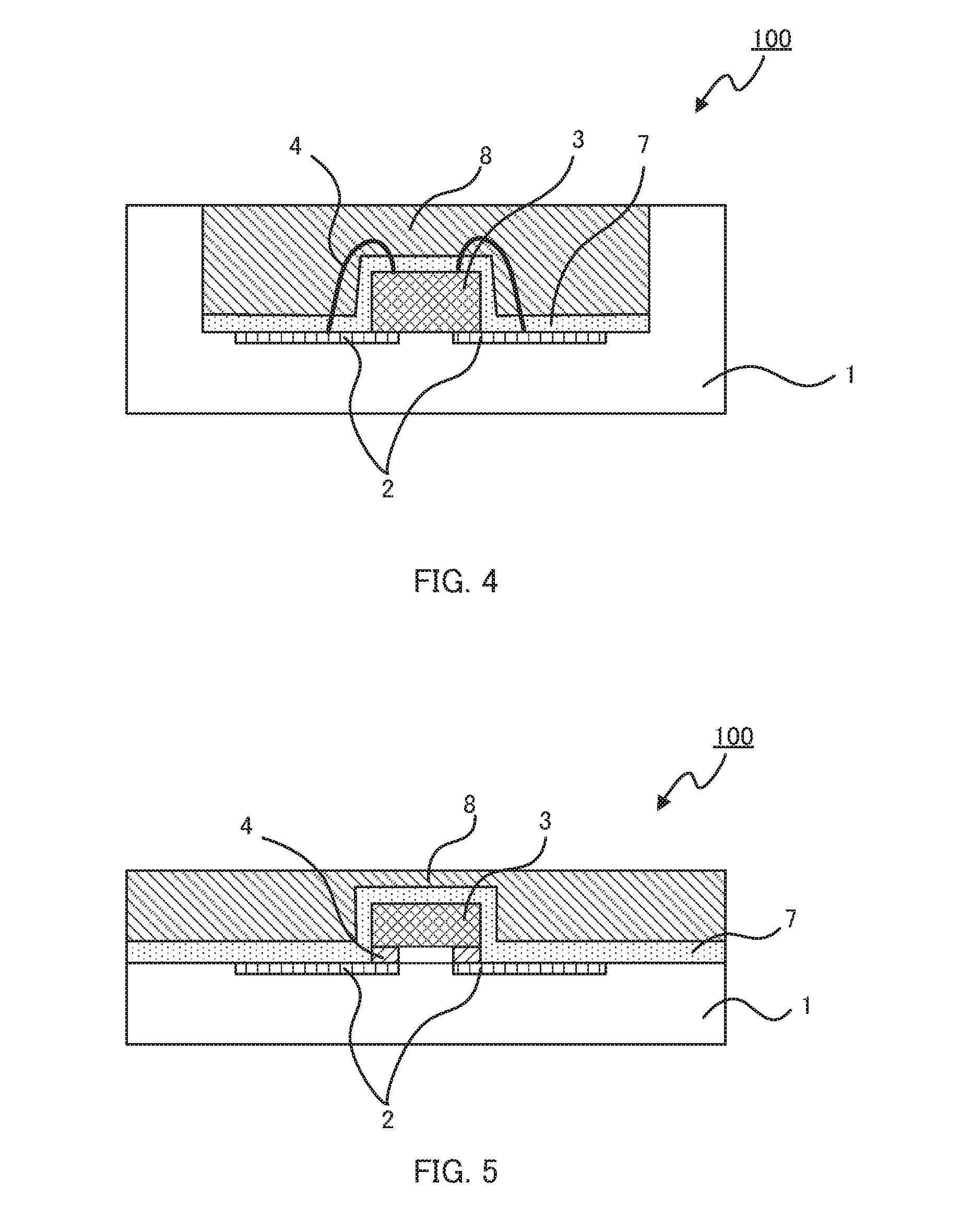
[0027]In the third LED device of the present invention, a metal in the primer layer forms a strong and firm metal-oxane bonding with a hydroxyl group present in a metal part of the LED element or a surface of the package, or a polysiloxane compound in the light transmissive layer. Therefore, in the LED device of the present invention, even when a load is applied due to changes in temperature, layer separation and the like dos not occur and heat resistance and gas barrier property are high.

Problems solved by technology

Therefore, when light emitted from the LED chip is incident to the transparent resin layer, interfacial reflection easily occurs, resulting in remarkable reduction in outcoupling efficiency (external quantum efficiency).
However, reflection occurs at an interface between the LED chip and the transparent resin layer, making it difficult to obtain sufficient outcoupling efficiency.
Therefore, as time passes, a metallic reflector on which the LED chip is mounted is eroded, and, thus, reflection efficiency is reduced and outcoupling efficiency from the LED device is also reduced.
However, the phenyl silicone resin does not yet have a sufficient sulfide gas resistance, and, thus, it has not been applied to exterior lighting devices that require high sulfide gas resistance.
Further, the phenyl silicone resin does not have sufficient adhesion, transparency, and light resistance.
In this LED device, the metallic reflector is coated with the inorganic material layer having low gas permeability, and, thus, the metallic reflector is not easily eroded.

Method used


Image

  • Sealant for LED device, LED device, and method for producing LED device
  • Sealant for LED device, LED device, and method for producing LED device
  • Sealant for LED device, LED device, and method for producing LED device

Examples


example 27

Production of LED Device 1-53

[0379]LED device 1-53 was obtained in the same manner as LED device 1-49 except that 2.0 g of slurry (SZR-M, produced by Sakai Chemical Industry Co., Ltd.) in which ZrO2 fine particles were dispersed was added to a sealant for an LED device.

example 28

Production of LED Device 1-54

[0380]LED device 1-54 was obtained in the same manner as LED device 1-50 except that 2.0 g of slurry (SZR-M, produced by Sakai Chemical Industry Co., Ltd.) in which ZrO2 fine particles were dispersed was added to a sealant for an LED device.

example 29

Production of LED Device 1-55

[0381]LED device 1-55 was obtained in the same manner as LED device 1-51 except that 2.0 g of slurry (SZR-M, produced by Sakai Chemical Industry Co., Ltd.) in which ZrO2 fine particles were dispersed was added to a sealant for an LED device.


PUM

PropertyMeasurementUnit
particle sizeaaaaaaaaaa
thicknessaaaaaaaaaa
wt %aaaaaaaaaa

Abstract

The objective of the present invention is to provide a sealant for an LED device capable of forming a sealing layer having a high level of light extraction, outstanding resistance to sulfidizing gas, and not giving rise to cracking or peeling even when used for extended periods, as well as an LED device employing the same. In order to attain at least one of the abovementioned objective, a sealant for an LED device reflecting one aspect of the present invention contains 100 mass parts of a 1000-3000 mass average molecular weight polysiloxane polymerized from a trifunctional monomethyl silane compound and a tetrafunctional silane compound, 5 mass parts to 100 mass parts of an organometallic compound comprising a metal alkoxide or metal chelate containing a Group 4 or Group 13 metal, and a solvent.

Description

TECHNICAL FIELD[0001]The present invention relates to a sealant for an LED device capable of sealing LED elements, an LED device, and a method for producing the LED device.BACKGROUND ART[0002]In recent years, there has been widely used an LED device in which a phosphor such as a YAG phosphor is disposed around a gallium nitride (GaN)-based blue light-emitting diode (LED) chip, and blue light emitted from the blue LED chip is mixed with yellow light emitted from the phosphor that has received the blue light, so that white light is obtained. Also, there has been developed an LED device in which various phosphors are disposed around a blue LED chip, and blue light emitted from the blue LED chip is mixed with red light and green light emitted from the phosphors that have received the blue light, so that white light is obtained.[0003]White LED devices have various applications and have been in demand as alternatives to fluorescent lamps and incandescent lamps. Such lighting devices are c...

Claims


Application Information

Patent Timeline
Patent Type & Authority Applications(United States)
IPC IPC(8): H01L33/56H01L33/00C09K3/10H01L33/50
CPCH01L33/56H01L2933/0091H01L2224/13H01L2224/48091H01L33/502H01L2933/005H01L2933/0041C09K3/1018H01L33/005H01L2224/8592H01L2924/00014H01L2924/181H01L2924/00012
Inventor YONEZAKI, AYUMIMOCHIZUKI, MAKOTO
Owner KONICA MINOLTA INC
Why Eureka
Try Eureka