Rotational ducted fan (RDF) propulsion system

Inactive Publication Date: 2015-08-13
SAMUELSON DEVIN GLENN
View PDF17 Cites 21 Cited by
  • Summary
  • Abstract
  • Description
  • Claims
  • Application Information

AI Technical Summary

Benefits of technology

[0047]In another advantageous embodiment, an aft-shroud comprises one mounting section that houses electrical controls and has mounting hanger bars for a hook and latch connection and engagement system of the two replaceable electrochemical storage aft-shroud segments, wherein the electrochemical storage segments of the aft-shroud having the effect of heat exchangers and electrical supply systems for the propulsion system.
[0048]It would be advantageous to provide a machine to convert electrical energy to thrust.
[0049]It would also be advantageous to provide an object to create a fluid pressure diffe

Problems solved by technology

Specific to aircraft fuel, there is a limited global supply of the natural resource of carbon based fuels such as oil.
In consideration of other hybrid systems or alternative biofuel systems, the problem of supply and dependence on these types of natural resources creates new economic challenges such as increased consumable costs due to competing markets, consumable shortages, or even climate disruptions.
Given the current path as the global economy increases the supply and demand of oil creates significant risks for economic stability internationally.
This strain stems from an imbalanced use of natural resources and too high of dependence on non-renewable energy sources.
The carbon footprint of aircraft is negatively impacting the environment from both an atmospheric output of propulsion exhaust, and the extraction and refinery processes of petroleum or biofuels.
Other problems that exist with combustion type systems include design restrictions to accommodate a safe combustible containment structure that facilitates the need for only using static fluid containment systems, thus limiting efficiency to be achieved primarily through focused attention to fluid density, achieved through compressors, entropy, and static nozzle designs historically.
No other solutions in existence today address the three problems that the rotational ducted

Method used


Image

  • Rotational ducted fan (RDF) propulsion system
  • Rotational ducted fan (RDF) propulsion system
  • Rotational ducted fan (RDF) propulsion system

Examples


Example

[0063]For purposes of clarity and brevity, like elements and components will bear the same designations and numbering throughout the Figures.

DESCRIPTION OF THE PREFERRED EMBODIMENT

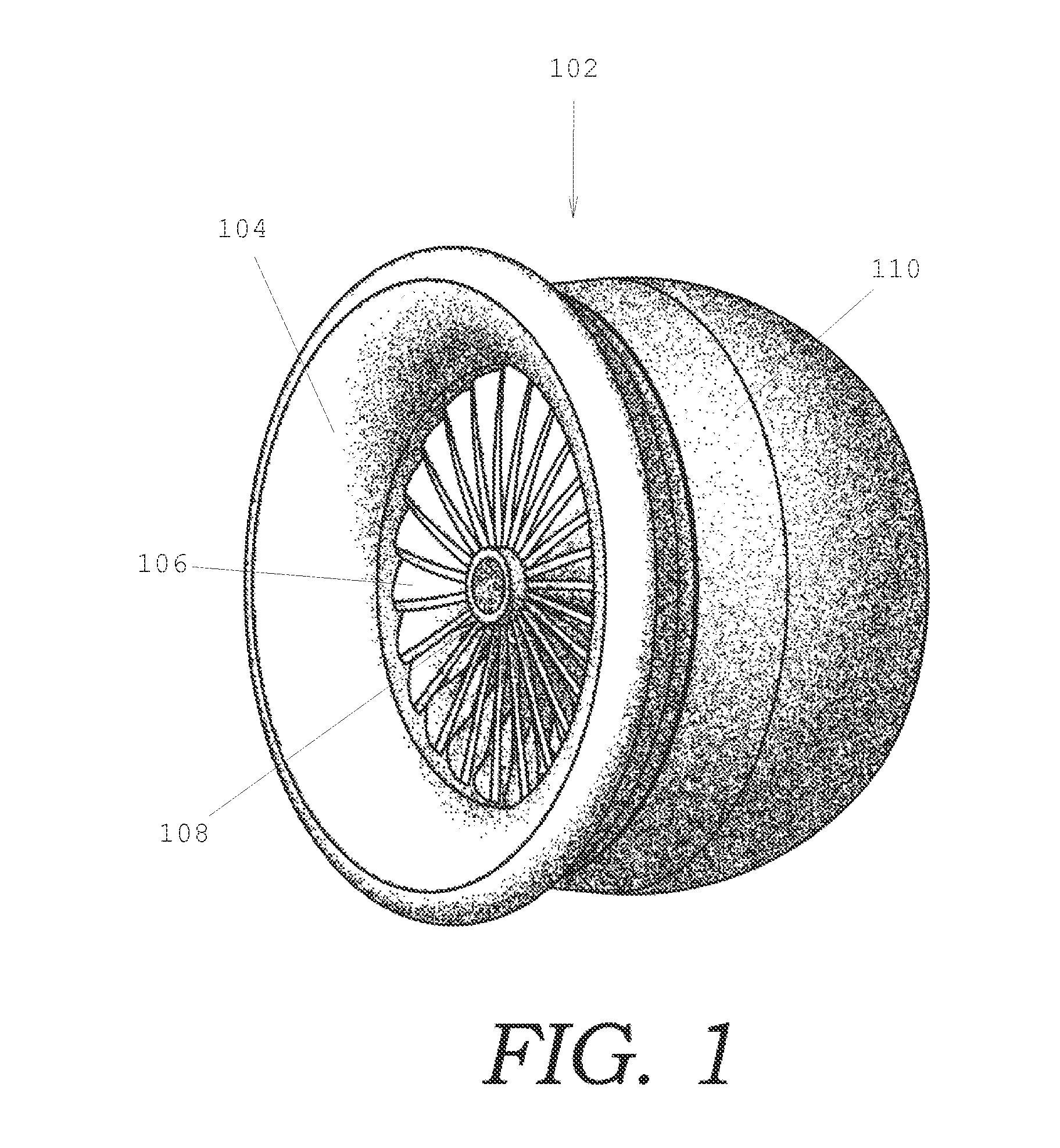
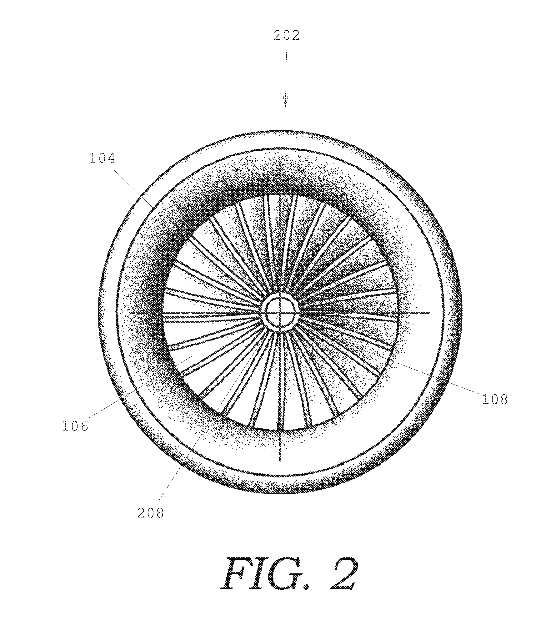
[0064]FIG. 1 is a perspective view of a rotational ducted fan motor. Referring more particularly to the drawings, embodiments of the disclosure may be described in the context of an aircraft propulsion system. The embodiment shown in FIG. 1 comprises a static non-rotating aft duct 110, and a rotational ducted fan 202. The rotational ducted fan is described as a dynamic rotor that rotates about an axis parallels to its thrust, and is comprised of an outer shroud or duct that is dynamic and rotates orbitally about a center axis that is parallel to its generally cylindrical shape, and concentric to a center hub and an arrangement of a plurality of propeller blades or airfoils axially perpendicular to the axis of rotation. The rotational ducted fan or orbital fan duct is comprised of a cylinder that has a plur...


PUM


Abstract

In accordance with the present invention, an embodiment of a rotational ducted fan motor comprises a monolithic rotational ducted fan rotor, an electric propulsion system, a static aft-shroud comprising electrochemical-energy-storage, and an engagement system. The rotational ducted fan rotor is the portion of a ducted fan motor comprising a propeller, a duct, and a center hub, and having the effect of increasing the pressure difference from upstream to downstream of the propeller. The electric propulsion system comprises permanent magnets affixed to the rotational ducted fan rotor, repelling magnetic coils affixed to the static aft-shroud and electrical power provided by the electrochemical-energy-storage comprised within the aft-shroud.

Description

RELATED APPLICATIONS[0001]The present application is a continuation application of U.S. patent application Ser. No. 14 / 095,737, filed Dec. 3, 2013, for ROTATIONAL DUCTED FAN, OR RDF FAN MOTOR, by Devin Glenn Samuelson, included by reference herein and for which benefit of the priority date is hereby claimed.FIELD OF THE INVENTION[0002]The present invention relates to an aircraft propulsion system, and more particularly to a novel rotational inlet shroud, and additionally to an energy storage and maintenance system.BACKGROUND OF THE INVENTION[0003]For each barrel of crude oil refined, approximately only 4 gallons of jet fuel are realized. Specific to aircraft fuel, there is a limited global supply of the natural resource of carbon based fuels such as oil. In consideration of other hybrid systems or alternative biofuel systems, the problem of supply and dependence on these types of natural resources creates new economic challenges such as increased consumable costs due to competing ma...

Claims


Application Information

Patent Timeline
IPC IPC(8): F01D25/16F01D15/10F01D25/24F01D25/00F01D25/28
CPCF01D25/164F01D25/005F01D15/10F01D25/24F01D25/28B64C11/001B64D27/24B64D29/02B64D29/04Y02T50/40Y02T50/60
Inventor SAMUELSON, DEVIN GLENN
Owner SAMUELSON DEVIN GLENN
Why Eureka
Try Eureka