Method for Improving Performance of Wavelength Beam Combining Diode Laser Systems

a wavelength beam and laser technology, applied in semiconductor lasers, laser details, laser optical resonator construction, etc., can solve the problems of slow turn-on time of output power of diode emitters operating in wbc systems, slow turn-on time output power of diode emitters if not designed properly, etc., to improve the turn-on time of the system, improve the reflectivity of output couplers, and improve the effect of system performan

Active Publication Date: 2015-08-13
PANASONIC OF NORTH AMERICA
View PDF5 Cites 9 Cited by
  • Summary
  • Abstract
  • Description
  • Claims
  • Application Information

AI Technical Summary

Benefits of technology

[0008]Disclosed is a method for fast turn-on time output power from a WBC laser system. The method can include using diode emitters at the optimized wavelength, optimized output coupler reflectivity, simmering the diode current, and reducing the junction temperature.
[0010]To further improve the turn-on time of the system the reflectivity of the output coupler can be optimized. Usually the reflectivity needs to be increased. Increasing the output coupler increases the locking range of the diode emitters. By increasing the locking range of the diode emitters the usable band can be increased accordingly.
[0012]In another aspect of this invention, to achieve fast turn-on power the junction temperature of the diode elements needs to be decreased. With this decrease there is a smaller change in gain shift, and thus, a useable or more useable wavelength range with fast turn-on time can be achieved. The decrease in junction temperature can be achieved by better heat sink of the diode elements or lowering the operating power.

Problems solved by technology

However, if the diode elements or emitters are not chosen or designed properly the output power turn-on time can be slow, such as ranging from milli-seconds (ms) to several seconds.
For material processing this not desirable and often the output power turn-on time needs to be in the micro-second time range.
These challenges are compounded when an increased power or high-power output is desired that requires combining multiple emitters.
Applicant has recognized that diode emitters operating in WBC systems will encounter slow turn-on time output power if not designed properly.
This turn-on time problem is due to the fact that when the laser system is turned on from zero output power to full operating power there is a large thermal induced gain shift at the junction of the diode emitters.
If the shift of the gain peak is larger than the gain bandwidth of the diode elements than the output power turn-on time will be slow.

Method used


Image

  • Method for Improving Performance of Wavelength Beam Combining Diode Laser Systems
  • Method for Improving Performance of Wavelength Beam Combining Diode Laser Systems
  • Method for Improving Performance of Wavelength Beam Combining Diode Laser Systems

Examples


Embodiment Construction

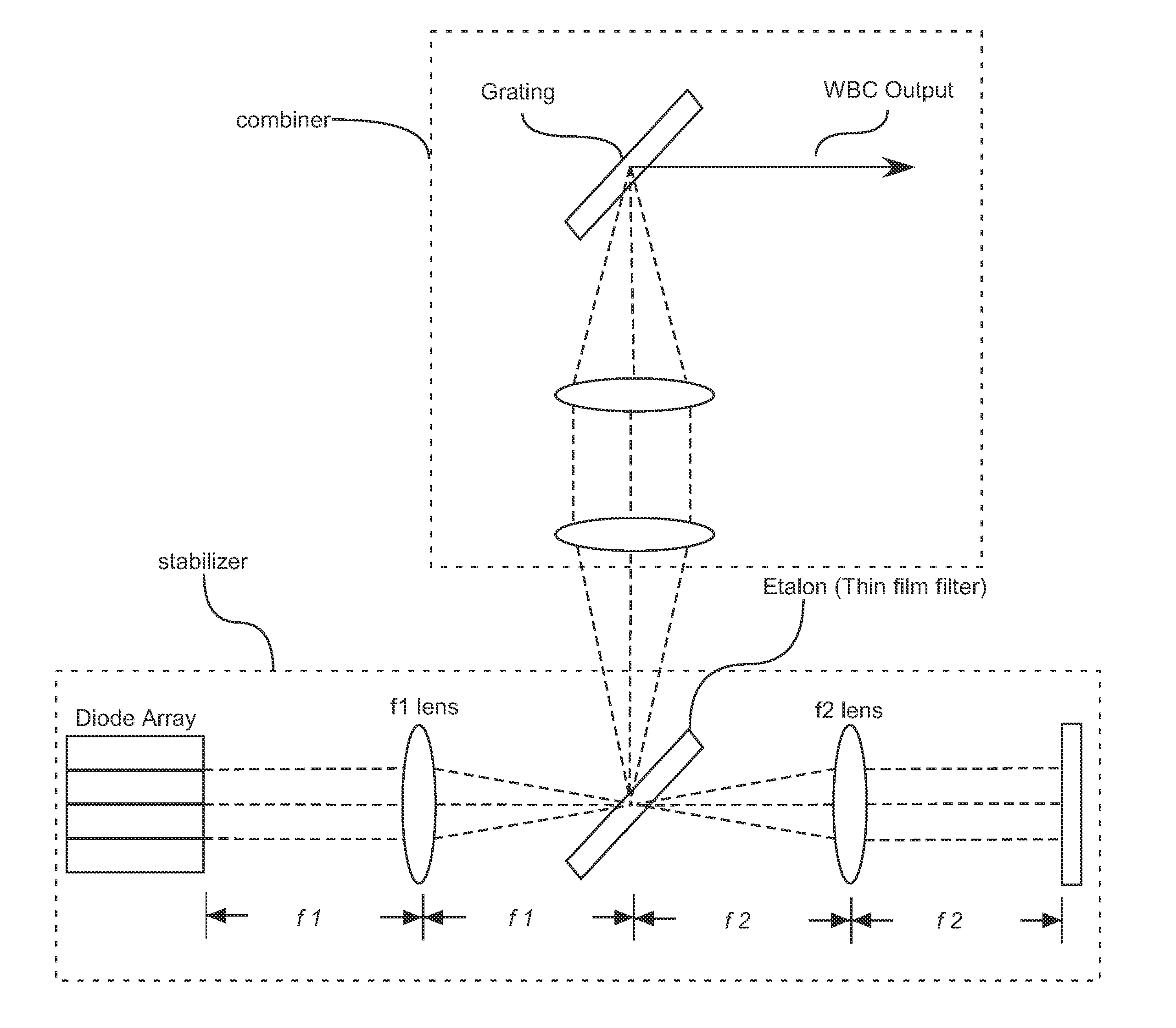
[0030]Aspects and embodiments relate generally to the field of creating a fast turn-on time WBC system through 1) pre-determining the optimal positioning of diode emitters, 2) determining an optimal reflectivity for the output coupler, 3) selecting an appropriate simmer current, 4) and selecting an optimal operating junction temperature of the diode emitters.

[0031]For purposes of this application a diode element can refer to a diode bar or diode emitter. A semiconductor gain element can include any electromagnetic beam-generating device, but may or may not be self-resonating. These include quantum cascade lasers (QCL) or elements, vertical cavity surface emitting laser (VCSEL) or elements, diode elements and the like. Generally each emitter is comprised of a back reflective surface, at least one optical gain medium, and a front reflective surface. The optical gain medium refers to increasing the gain of electromagnetic radiation and is not limited to the visual, IR or ultraviolet po...


PUM


Abstract

A method for optimizing startup time and efficiency for a WBC laser diode system having numerous diode elements, wherein each diode element is measured, an optimal band region is determined for each diode element, and placed in an optimal placement within an array of diode elements.

Description

COPYRIGHT INFORMATION[0001]A portion of the disclosure of this patent document contains material that is subject to copyright protection. The copyright owner has no objection to the facsimile reproduction by anyone of the patent document or the patent disclosure, as it appears in the Patent and Trademark Office patent file or records, but otherwise reserves all copyright rights whatsoever.PRIORITY CLAIMS[0002]This application claims benefit to U.S. Provisional Patent Application No. 61 / 916,598 being filed Dec. 16, 2013, which is hereby incorporated by reference in its entirety.BACKGROUND OF THE INVENTION[0003]1. Field of the Invention[0004]The present embodiments relate generally to Wavelength Beam Combining (WBC) systems and methods for improving the desired output power turn-on time.[0005]2. Description of the Prior Art[0006]When diode emitters or elements are used in WBC systems they have the advantage of generally being more efficient than all other types of lasers. However, if ...

Claims


Application Information

Patent Timeline
Patent Type & Authority Applications(United States)
IPC IPC(8): H01S5/00H01S5/0687
CPCH01S5/005H01S5/0687H01S5/4012H01S3/13H01S5/4087H01S3/1306H01S5/068H01S5/0683H01S5/141H01S5/14H01S5/4062H01S3/08059H01S5/02469H01S5/06804
Inventor TAYEBATI, PARVIZCHANN, BIENNHUANG, ROBINLOCHMAN, BRYAN JOHNVILLARREAL-SAUCEDO, FRANCISCO JAVIERZAMBUTO, JAMES JOSEPH
Owner PANASONIC OF NORTH AMERICA
Why Eureka
Try Eureka