Method for eutectic bonding of two carrier devices

a carrier device and eutectic bonding technology, applied in the direction of instruments, soldering apparatus, semiconductor/solid-state device details, etc., can solve the problems of limited interdiffusion of germanium and aluminum required for the bonding process, homogeneity and reliability, and impair the bonding adhesion, etc., to achieve the effect of improving the eutectic bonding method

Inactive Publication Date: 2015-08-20
ROBERT BOSCH GMBH
View PDF1 Cites 10 Cited by
  • Summary
  • Abstract
  • Description
  • Claims
  • Application Information

AI Technical Summary

Benefits of technology

[0018]It is an object of the present invention

Problems solved by technology

It is true, however, that several effects are able to impair the homogeneity and the reliability of the bonding process:At contact with air, both germanium and aluminum form oxidized surface areas which are able to impair bonding adhesion.Both surfaces of bonding materials aluminum and germanium have a certain basic roughness, by which an effective geometrical contact area between the two surfaces is reduced, first of all, so that even the interdiffusion of germanium and aluminum required for the bonding process is limited.
However, too high a bonding pressure may lead disadvantageously to damage in the wafer structure.Particularly for acceleration sensors, frequently so-called anti-striction coatings (ASC

Method used


Image

  • Method for eutectic bonding of two carrier devices
  • Method for eutectic bonding of two carrier devices
  • Method for eutectic bonding of two carrier devices

Examples


Embodiment Construction

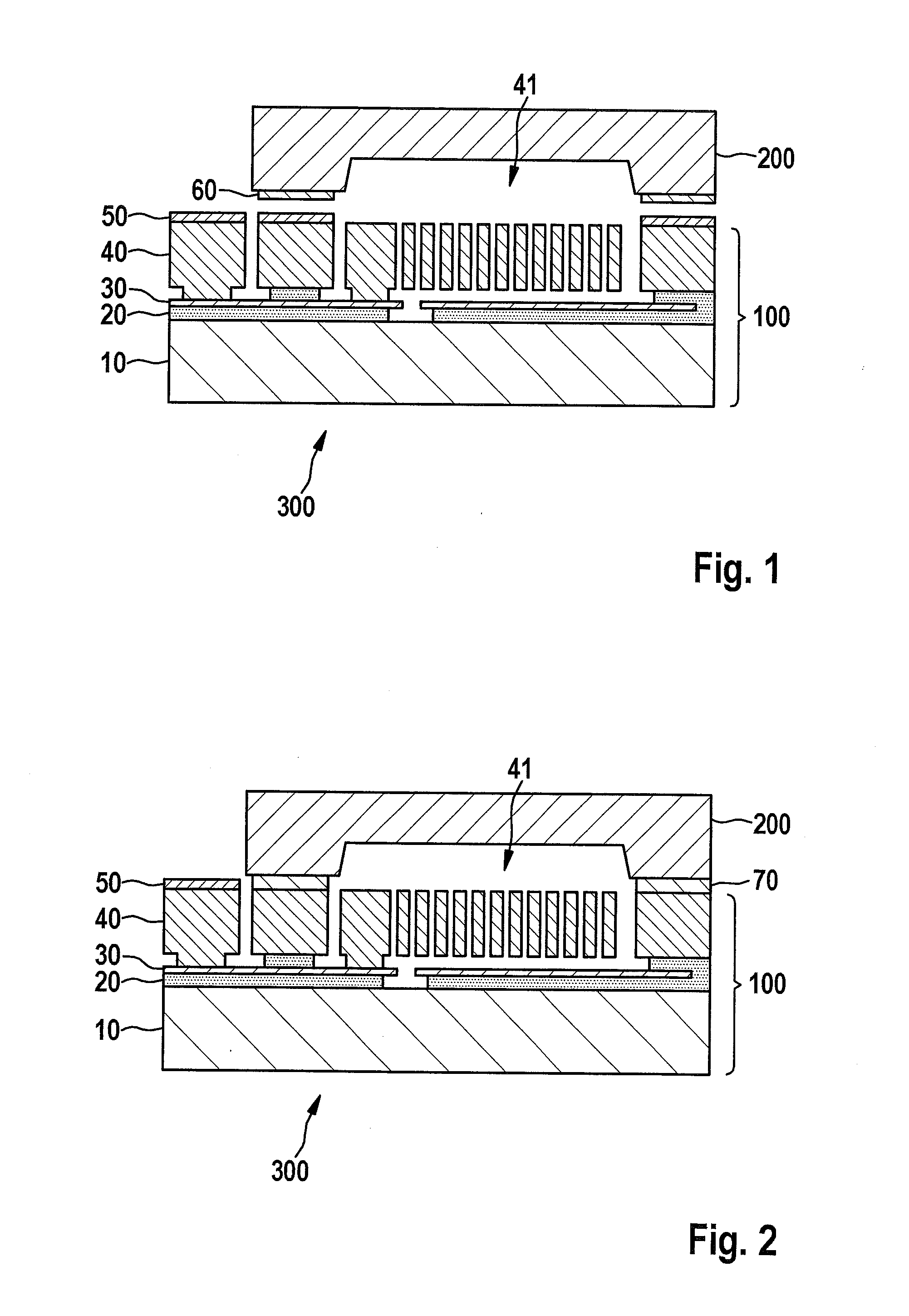
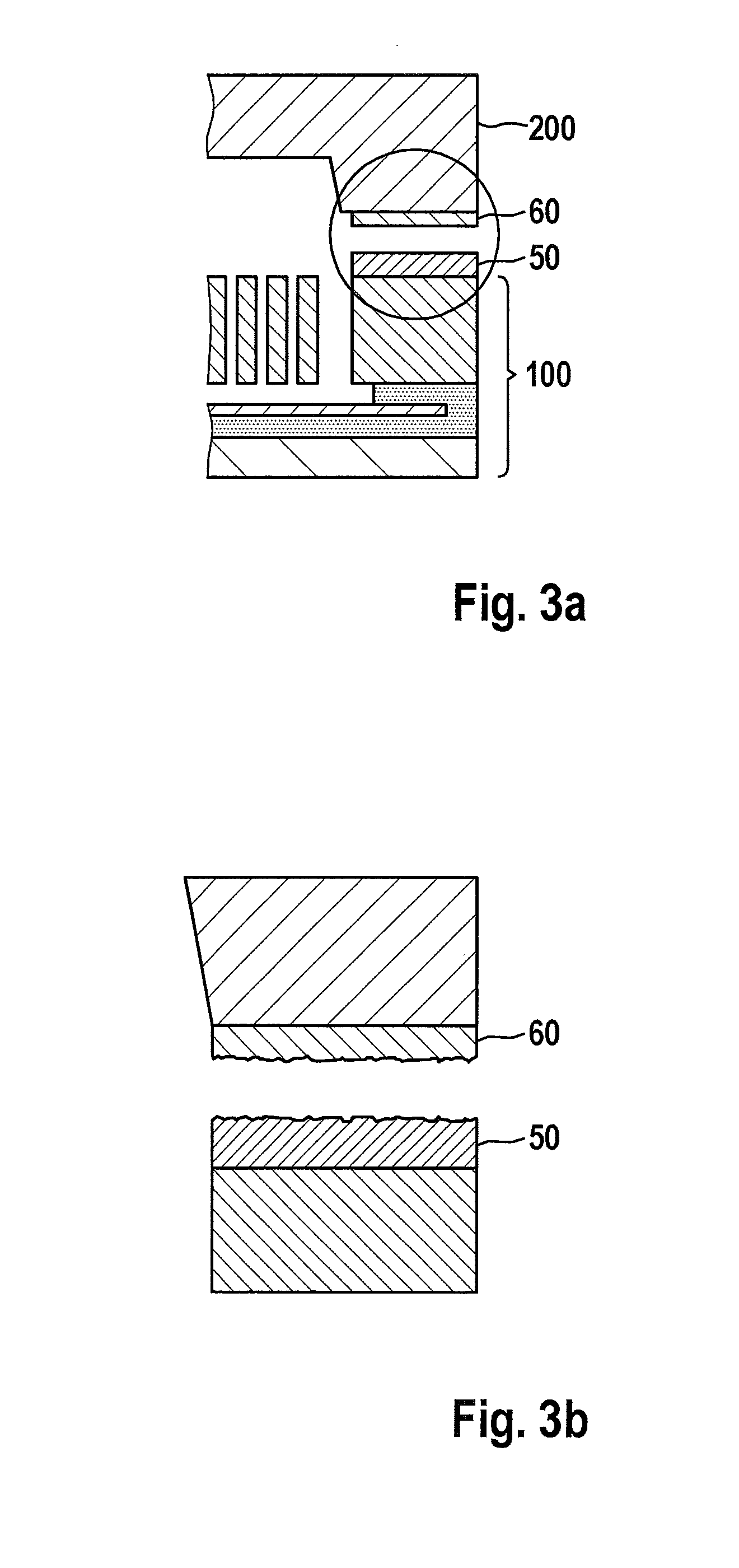
[0043]FIG. 2 shows a cross sectional view of a conventional eutectically bonded micromechanical sensor element 300 having two carrier devices 100, 200. A eutectic 70 is visible, which is developed as a metallic aluminum-germanium structure. Eutectic 70 forms an hermetic sealing ring around micromechanical patterns 41 of MEMS wafer 100, as well as electrical contacts between MEMS wafer 100 and cap wafer 200, if layers 50, 60 of the two bonding materials are connected electrically conductively to thick functional layer 40 and cap wafer 200.

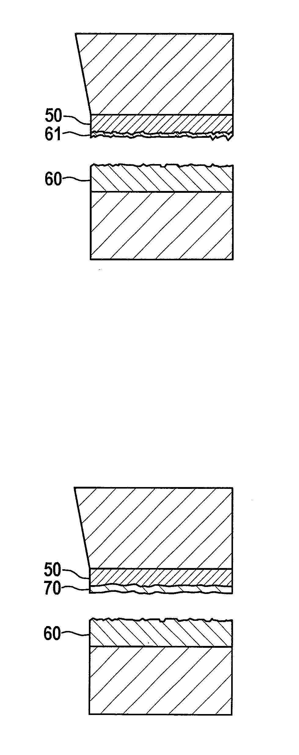
[0044]FIG. 3a shows a section, emphasized by a circular frame, of the two bonding regions having a first layer 50 of a first bonding material (e.g. aluminum) and a second layer 60 of a second bonding material (e.g. germanium). FIG. 3 shows the emphasized area of FIG. 3a basically greatly enlarged. One may see that surfaces of layers 50, 60 are able to have considerable surface roughness, and therefore permit only an incomplete, partially only point-...


PUM

PropertyMeasurementUnit
Thicknessaaaaaaaaaa

Abstract

A method for eutectic bonding of two carrier devices, including the tasks of putting a first layer of a first bonding material on the first carrier device, putting a first layer of a second bonding material on the second carrier device, putting a second layer of the second bonding material, that is thin in relation to the first layer of the first bonding material, on the first layer of the first bonding material, and providing the eutectic bonding of the two carrier devices.

Description

RELATED APPLICATION INFORMATION[0001]The present application claims priority to and the benefit of German patent application no. 10 2014 202 808.6, which was filed in Germany on Feb. 17, 2014, the disclosure of which is incorporated herein by reference.FIELD OF THE INVENTION[0002]The present invention relates to a method for eutectic bonding of two carrier devices. The present invention also relates to a micromechanical component.BACKGROUND INFORMATION[0003]Micromechanical sensors for measuring acceleration and rotational speed, for example, are believed to be understood and produced in mass production in the automobile and consumer field.[0004]FIG. 1 shows a basic cross-sectional view of a conventional micromechanical inertial sensor 300. In this context, oxide layers 20 and polysilicon layers 30 are deposited and patterned on a silicon substrate 10. In a thick functional layer 40, movable micromechanical patterns 41 are provided. The buried polysilicon layer 30 is used as an elect...

Claims


Application Information

Patent Timeline
IPC IPC(8): B81C1/00B23K1/20B81B7/00B23K1/00
CPCB81C1/0023B81B7/008B23K1/20B23K1/0016B81C2203/035B81C1/00269B81B2201/0235B81B2207/012B81C2203/0118
Inventor CLASSEN, JOHANNES
Owner ROBERT BOSCH GMBH
Why Eureka
Try Eureka