Microwave power amplification apparatus and method thereof

a technology of micro-wave power and amplifier, which is applied in the direction of instruments, semiconductor lasers, optics, etc., can solve the problems of affecting the quality of received signals, too much input optical power damage to photodetectors, and inability to meet the vast capacity demand for data transmission, etc., to improve the signal detection sensitivity of communication networks, improve the quality of microwave quality and bit-error ratio, and improve the network transmission efficiency

Active Publication Date: 2015-08-27
NAT CHENG KUNG UNIV
View PDF3 Cites 9 Cited by
  • Summary
  • Abstract
  • Description
  • Claims
  • Application Information

AI Technical Summary

Benefits of technology

[0009]Another purpose of the present invention is to provide a method for microwave power amplification in the RoF networks through optical modulation depth improvement by applying period-one nonlinear dynamics of semiconductor lasers. In this manner, similar and even improved microwave quality and bit-error ratio (BER) are obtained, which shall enhance the signal detection sensitivity of communication networks, the transmission distance of optical fibers, and the network transmission efficiency.

Problems solved by technology
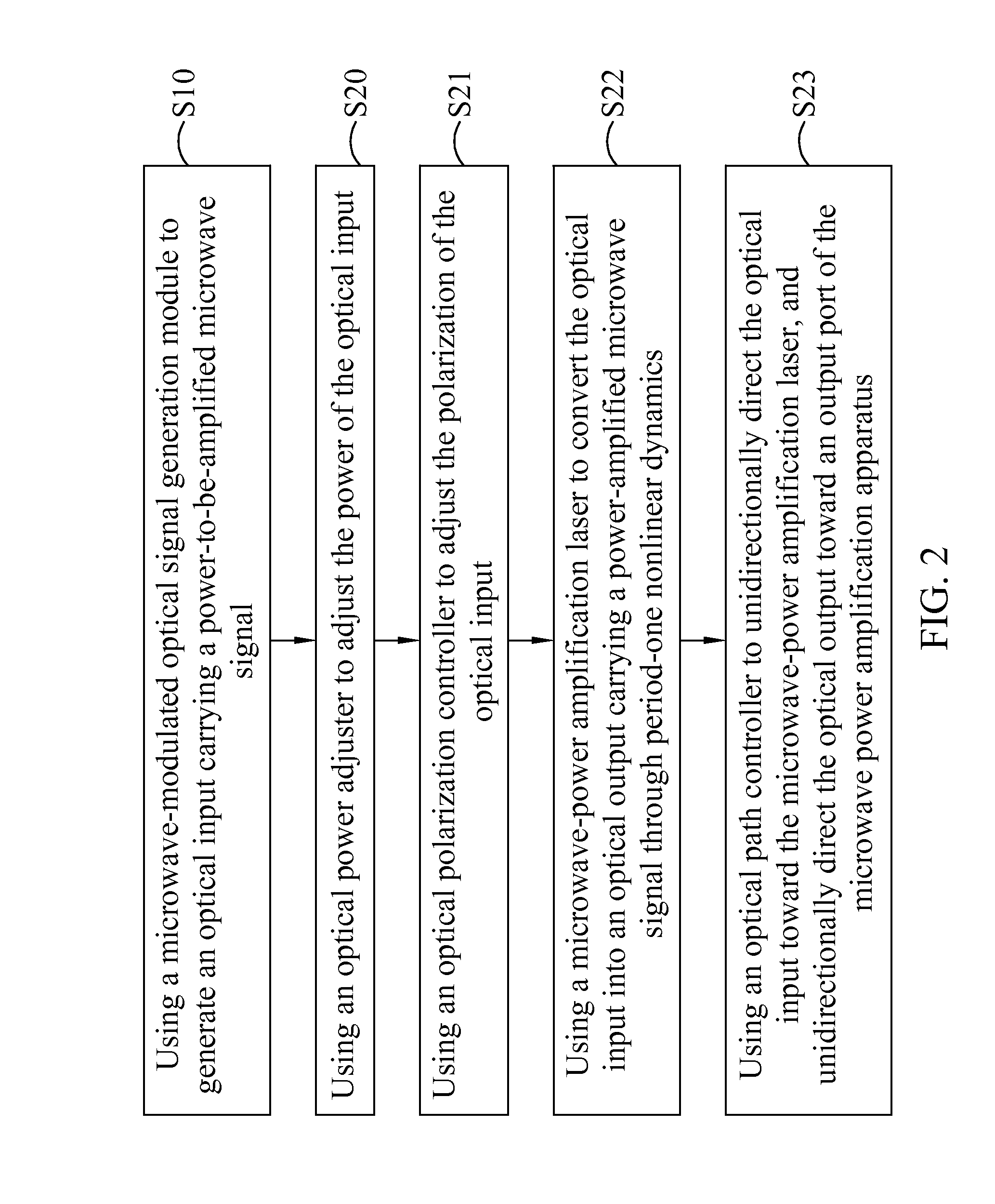
If the wireless networks are required to manage both the front-end data transmission between users and wireless base stations and the back-end data transmission between the wireless base stations and central offices, currently developed broadband wireless technologies are not capable of meeting the vast capacity demand for data transmission when the wireless networks are simultaneously accessed by a variety of different users or devices.
However, too much of the input optical power would damage the photodetectors.
However, nonlinear effects, such as harmonic or intermodulation distortion, are generally induced, which affect the quality of the received signals.
This, however, considerably reduces the overall power of the optical signal and therefore requires extra optical power amplifiers to compensate for the power loss.

Method used


Image

  • Microwave power amplification apparatus and method thereof
  • Microwave power amplification apparatus and method thereof
  • Microwave power amplification apparatus and method thereof

Examples


Embodiment Construction

[0037]To illustrate the device structure, operating principle, and advantageous characteristics of the present invention, a preferred embodiment and the corresponding drawings are provided with more details. The purpose of the drawings being used is for illustration, and they are not necessarily the real proportion and precise allocation of the embodiments of the present invention. Therefore, they should not be used to limit the privilege coverage of the practical embodiments of the present invention.

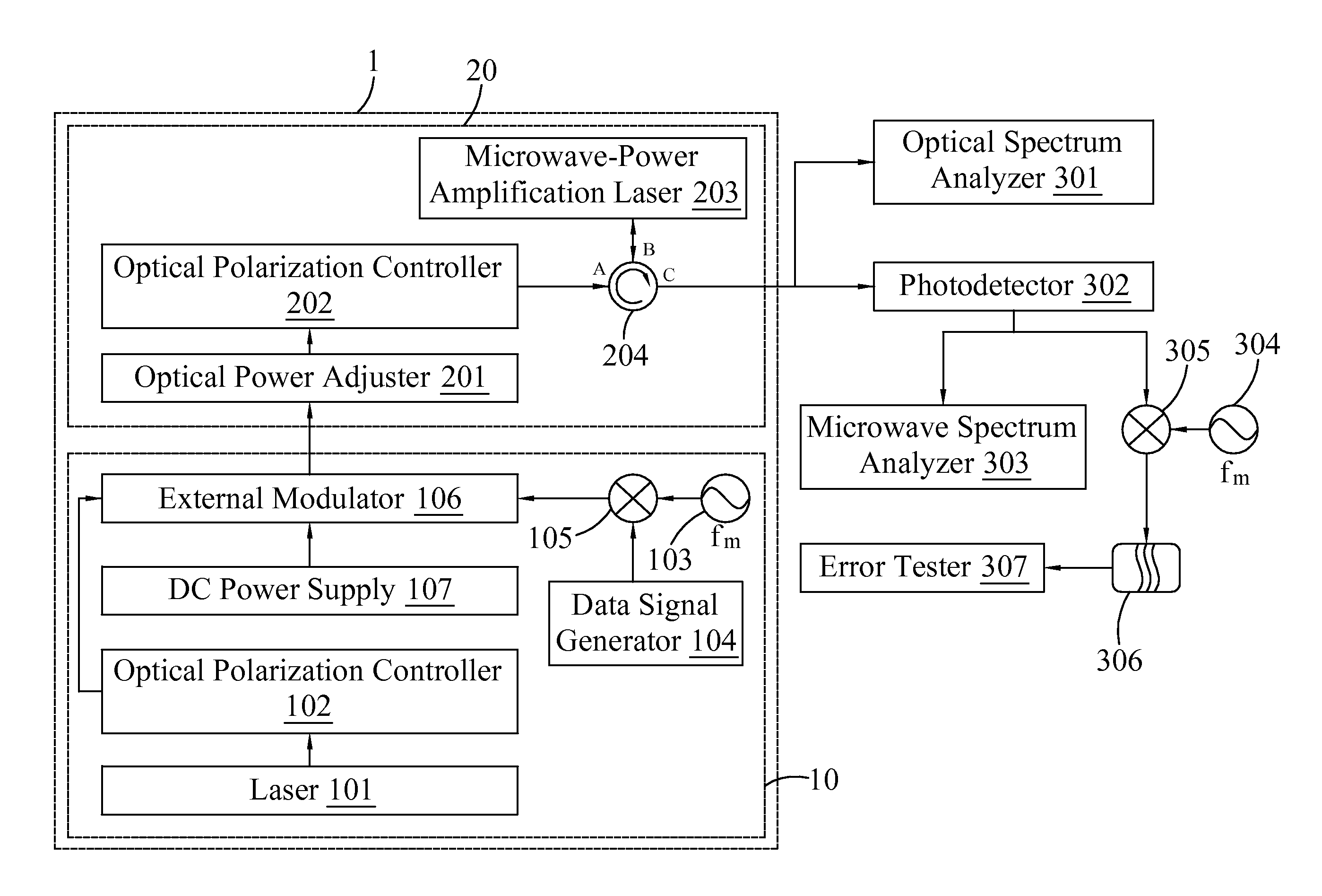
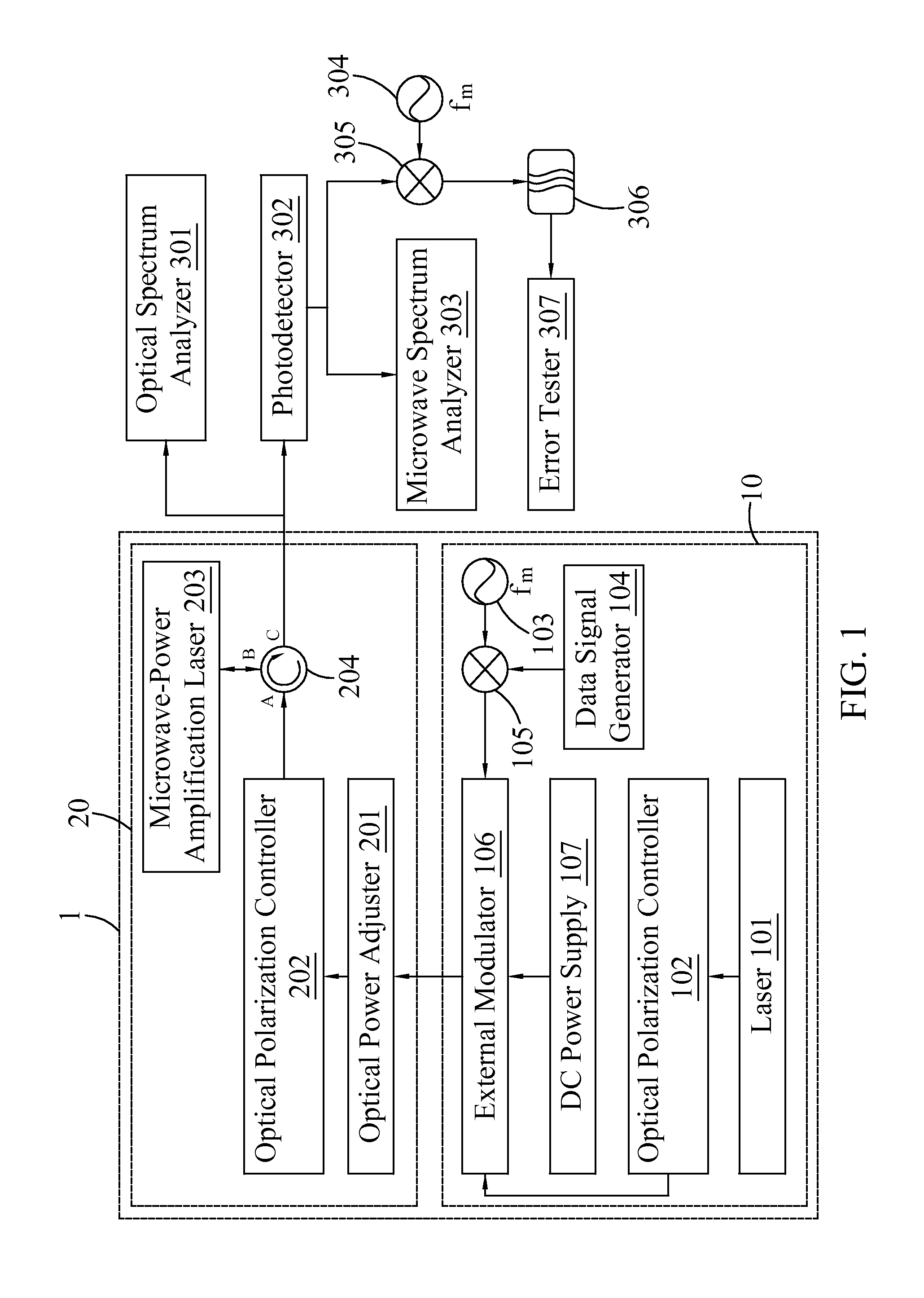
[0038]Referring to FIG. 1, FIG. 1 is a schematic representation of a microwave power amplification apparatus according to a preferred embodiment of the present invention. In FIG. 1, a microwave power amplification apparatus 1 includes a microwave power amplification module 20. The optical input of the microwave power amplification module 20 is an optical signal carrying a power-to-be amplified microwave signal and has at least one modulation sideband. The microwave power amplification m...


PUM


Abstract

Period-one nonlinear dynamics of semiconductor lasers are utilized to provide an apparatus for photonic microwave power amplification in radio-over-fiber links through optical modulation depth improvement. The microwave power amplification apparatus includes a microwave-modulated optical signal generation module and a microwave power amplification module. The amplification capability of the present microwave power amplification apparatus covers a broad microwave range, from less than 25 GHz to more than 60 GHz, and a wide gain range, from less than 10 dB to more than 30 dB. The microwave phase quality is mainly preserved while the microwave power is largely amplified, improving the signal-to-noise ratio up to at least 25 dB. The bit-error ratio at 1.25 Gb/s is better than 10−9 and a sensitivity improvement of up to at least 15 dB is feasible.

Description

CROSS-REFERENCE TO RELATED APPLICATION[0001]This application claims priority from Taiwan Patent Application No. 103106710, filed on Feb. 27, 2014 in Taiwan Intellectual Property Office, the contents of which are hereby incorporated by reference in their entirety.BACKGROUND OF THE INVENTION[0002]1. Field of the Invention[0003]The present invention relates to a microwave power amplification apparatus and method thereof by using, particularly, period-one nonlinear dynamics of semiconductor lasers.[0004]2. Description of the Related Art[0005]Communication networks are generally classified into wireless networks and wireline networks. In the wireless networks, microwaves are used as carriers to deliver data through air to provide communication between mobile electronic devices. In the wireline networks based on optical technologies, optical waves function as carriers to deliver data through optical fibers to provide communication between immobilized electronic devices. These two networks...

Claims


Application Information

Patent Timeline
Patent Type & Authority Applications(United States)
IPC IPC(8): H03F3/08H03F3/21
CPCH01S5/0623G02F1/3538H03F2200/393H03F3/21H03F3/08H01S5/5054H04B10/25759
Inventor HWANG, SHENG-KWANGHUNG, YU-HAN
Owner NAT CHENG KUNG UNIV
Why Eureka
Try Eureka