Fuel cell module

a fuel cell and module technology, applied in the direction of cell components, sustainable manufacturing/processing, electrochemical generators, etc., can solve the problems of inefficient heat quantity for raising the temperature of oxygen-containing gas supplied to the fuel cell stack, low efficiency, and a tendency to suffer from considerable pressure loss, etc., to achieve simple and compact structure, improve heat efficiency, and facilitate thermal self-sustaining operation

Active Publication Date: 2015-09-10
HONDA MOTOR CO LTD
View PDF2 Cites 3 Cited by
  • Summary
  • Abstract
  • Description
  • Claims
  • Application Information

AI Technical Summary

Benefits of technology

[0015]In the structure, heat waste and heat radiation are suppressed suitably. Thus, improvement in the heat efficiency is achieved, and thermally self-sustaining operation is facilitated. Further, simple and compact structure is achieved in the entire fuel cell module. The thermally self-sustaining operation herein means operation where the operating temperature of the fuel cel...

Problems solved by technology

Therefore, the quantity of heat for raising the temperature of the oxygen-containing gas supplied to the fuel cell stack 1a tends to be inefficie...

Method used


Image

  • Fuel cell module
  • Fuel cell module
  • Fuel cell module

Examples


first embodiment

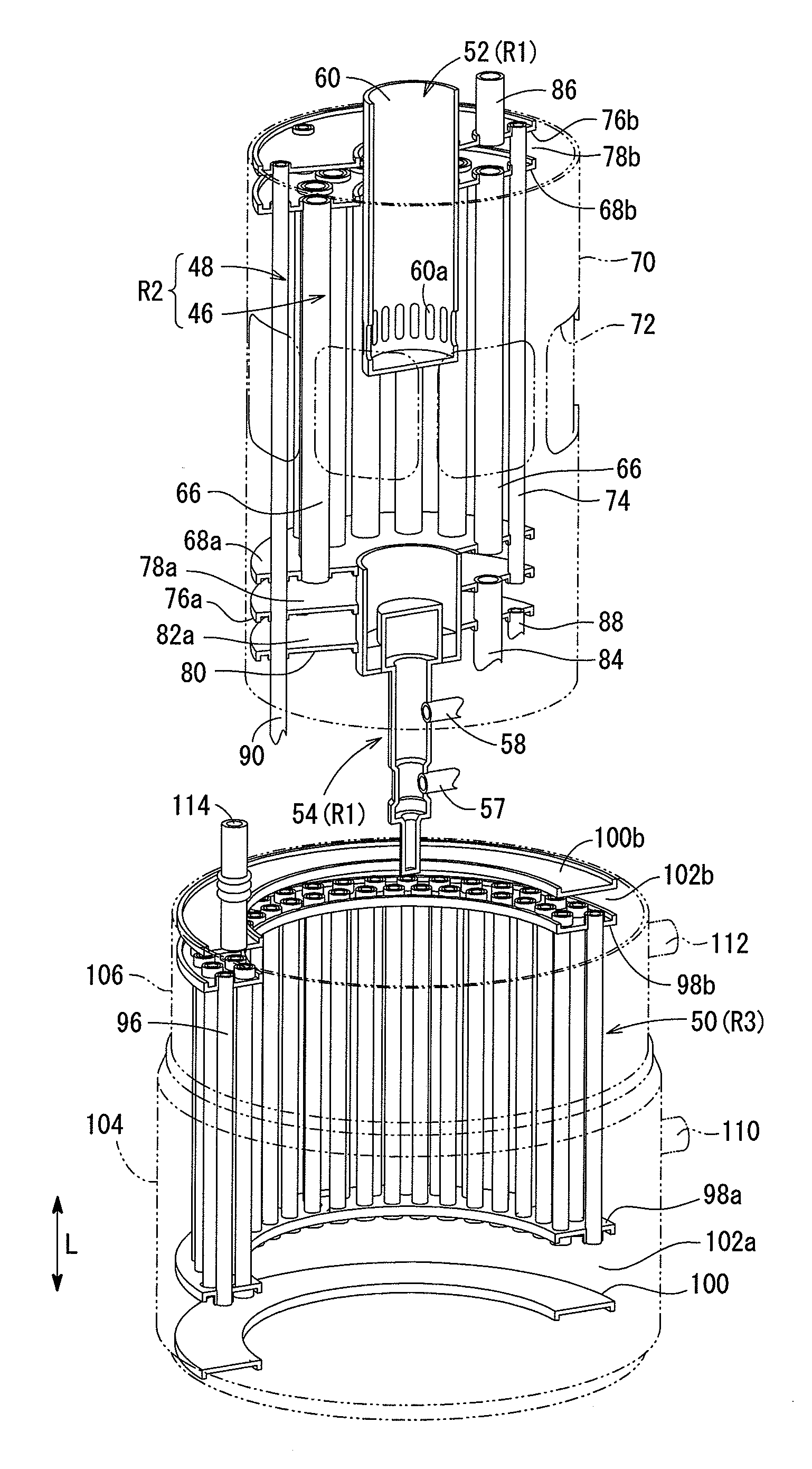
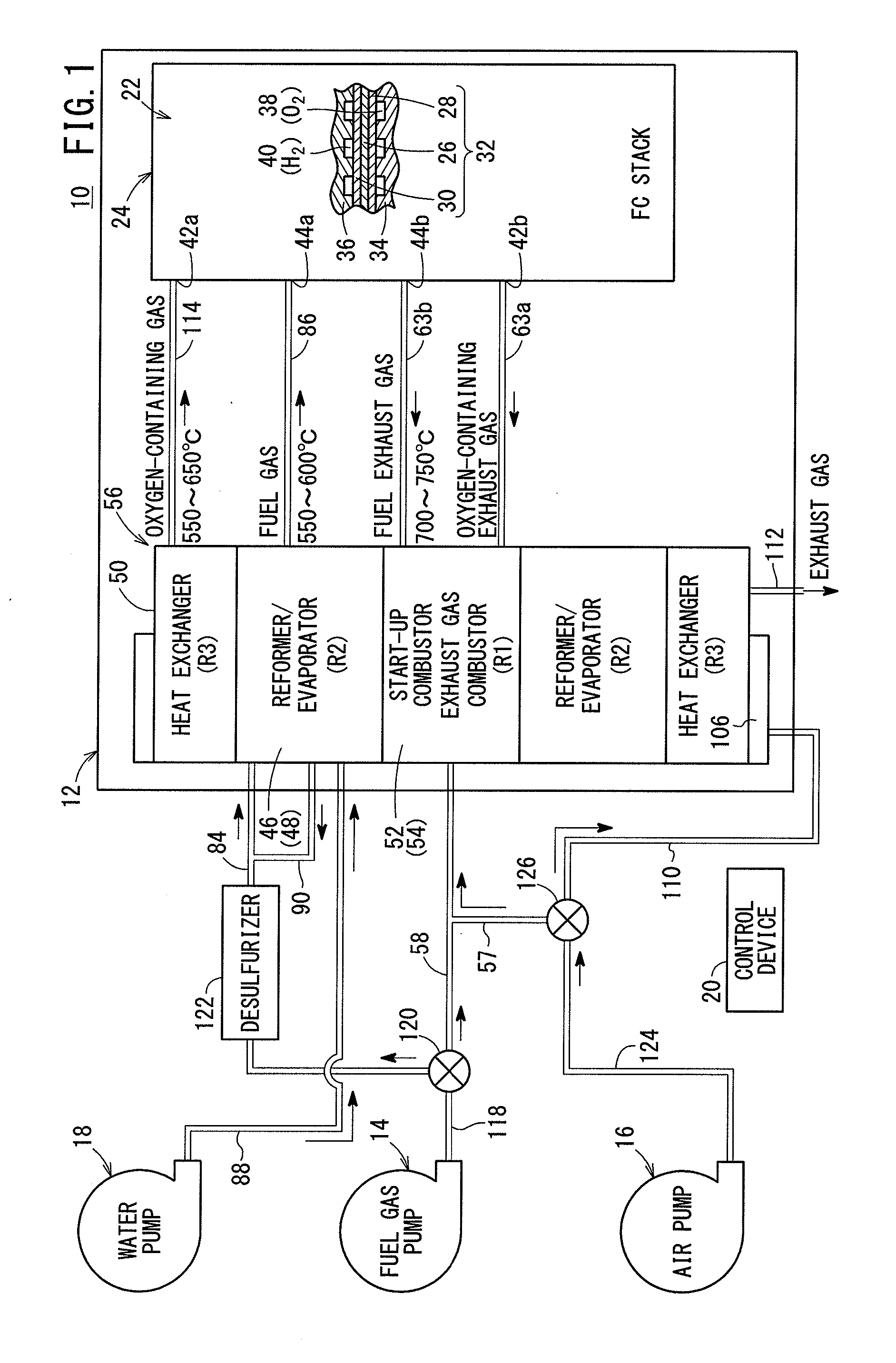
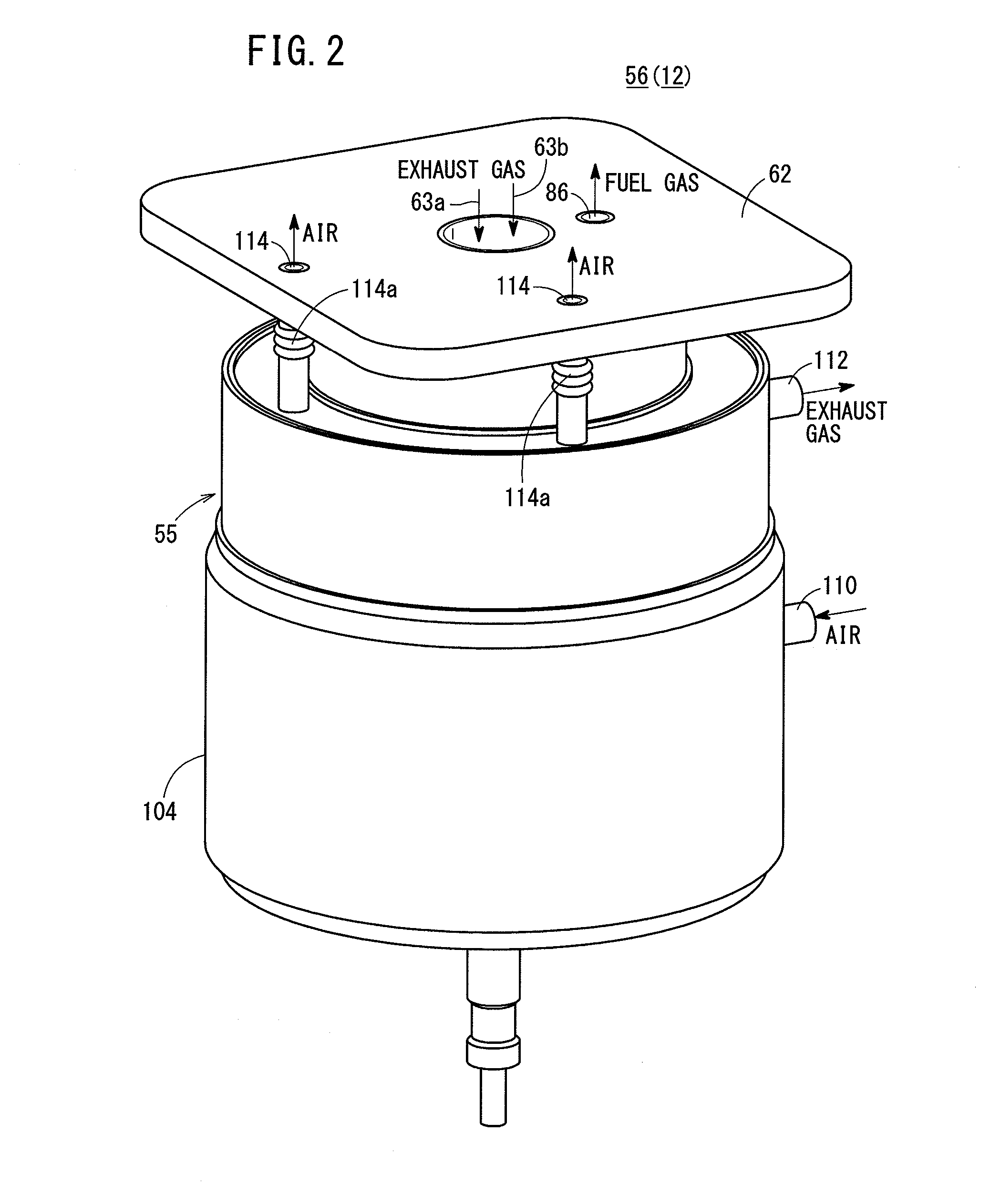
[0030]As shown in FIG. 1, a fuel cell system 10 includes a fuel cell module 12 according to the present invention, and the fuel cell system 10 is used in various applications, including stationary and mobile applications. For example, the fuel cell system 10 is mounted on a vehicle.

[0031]The fuel cell system 10 includes the fuel cell module (SOFC module) 12 for generating electrical energy in power generation by electrochemical reactions of a fuel gas (a gas produced by mixing a hydrogen gas, methane, and carbon monoxide) and an oxygen-containing gas (air), a raw fuel supply apparatus (including a fuel gas pump) 14 for supplying a raw fuel (e.g., city gas) to the fuel cell module 12, an oxygen-containing gas supply apparatus (including an air pump) 16 for supplying the oxygen-containing gas to the fuel cell module 12, a water supply apparatus (including a water pump) 18 for supplying water to the fuel cell module 12, and a control device 20 for controlling the amount of electrical e...

second embodiment

[0102]FIG. 8 is a diagram schematically showing structure of a fuel cell system 130 including a fuel cell module 132 according to the present invention.

[0103]The constituent elements of the fuel cell system 130 including the fuel cell module 132 according to the second embodiment of the present invention that are identical to those of the fuel cell system 10 including the fuel cell module 12 according to the first embodiment are labeled with the same reference numeral, and description thereof will be omitted.

[0104]As shown in FIGS. 8 and 9, FC peripheral equipment 134 of the fuel cell module 132 includes a heat recovery area 136 around the third area R3. As shown in FIG. 9, the heat recovery area 136 is formed independently of the oxygen-containing gas supply chamber 102a (i.e., such that the heat recovery area 136 is in non-communication with the oxygen-containing gas supply chamber 102a). That is, the holes 108 are not provided in the lower marginal end portion of the outer member...


PUM


Abstract

A fuel cell module includes a first area where an exhaust gas combustor and a start-up combustor are provided, an annular second area around the first area and where a reformer and an evaporator are provided, an annular third area around the second area and where a heat exchanger is provided, and an annular heat recovery area around the third area as a passage of oxygen-containing gas for recovery of heat radiated from the third area toward the outer circumference.

Description

TECHNICAL FIELD[0001]The present invention relates to a fuel cell module including a fuel cell stack formed by stacking a plurality of fuel cells for generating electricity by electrochemical reactions of a fuel gas and an oxygen-containing gas.BACKGROUND ART[0002]Typically, a solid oxide fuel cell (SOFC) employs a solid electrolyte of ion-conductive solid oxide such as stabilized zirconia. The solid electrolyte is interposed between an anode and a cathode to form an electrolyte electrode assembly (hereinafter also referred to as MEA). The electrolyte electrode assembly is sandwiched between separators (bipolar plates). In use, generally, predetermined numbers of the electrolyte electrode assemblies and the separators are stacked together to form a fuel cell stack.[0003]As a system including this type of fuel cell stack, for example, a fuel cell battery disclosed in Japanese Laid-Open Patent Publication No. 2001-236980 (hereinafter referred to as the conventional technique 1) is kno...

Claims


Application Information

Patent Timeline
IPC IPC(8): H01M8/04H01M8/06H01M8/12H01M8/24
CPCH01M8/04074H01M8/24H01M8/0631H01M8/0618H01M2300/0071H01M8/04022H01M8/12H01M2008/1293H01M8/04268B01J8/067B01J2208/00221B01J2208/00504B01J2208/0053B01J2208/00548B01J2208/00716C01B3/384C01B2203/0233C01B2203/066C01B2203/1288C01B2203/82H01M8/243H01M8/2483Y02E60/50Y02P20/10Y02P20/129H01M8/2425
Inventor YOSHIMINE, YUKIOGAWA, TETSUYA
Owner HONDA MOTOR CO LTD
Why Eureka
Try Eureka