Zero-emission, closed-loop hybrid solar-syngas otr power cycle

Inactive Publication Date: 2015-09-17
KING FAHD UNIVERSITY OF PETROLEUM AND MINERALS
View PDF10 Cites 14 Cited by
  • Summary
  • Abstract
  • Description
  • Claims
  • Application Information

AI Technical Summary

Benefits of technology

[0027]In another embodiment the method includes separating H2O from CO2 through one or more condensers. In another embo

Problems solved by technology

This results in increasing the amount of NOx in the exhaust gases.
In addition, because nitrogen has a high capacity to absorb heat, it absorbs energy and as a result, the combustion efficiency is reduced.
There are a lot of associated problems with the fossil fu

Method used


Image

  • Zero-emission, closed-loop hybrid solar-syngas otr power cycle
  • Zero-emission, closed-loop hybrid solar-syngas otr power cycle

Examples


Embodiment Construction

[0030]Referring now to the drawings, wherein like reference numerals designate identical or corresponding parts throughout the several views.

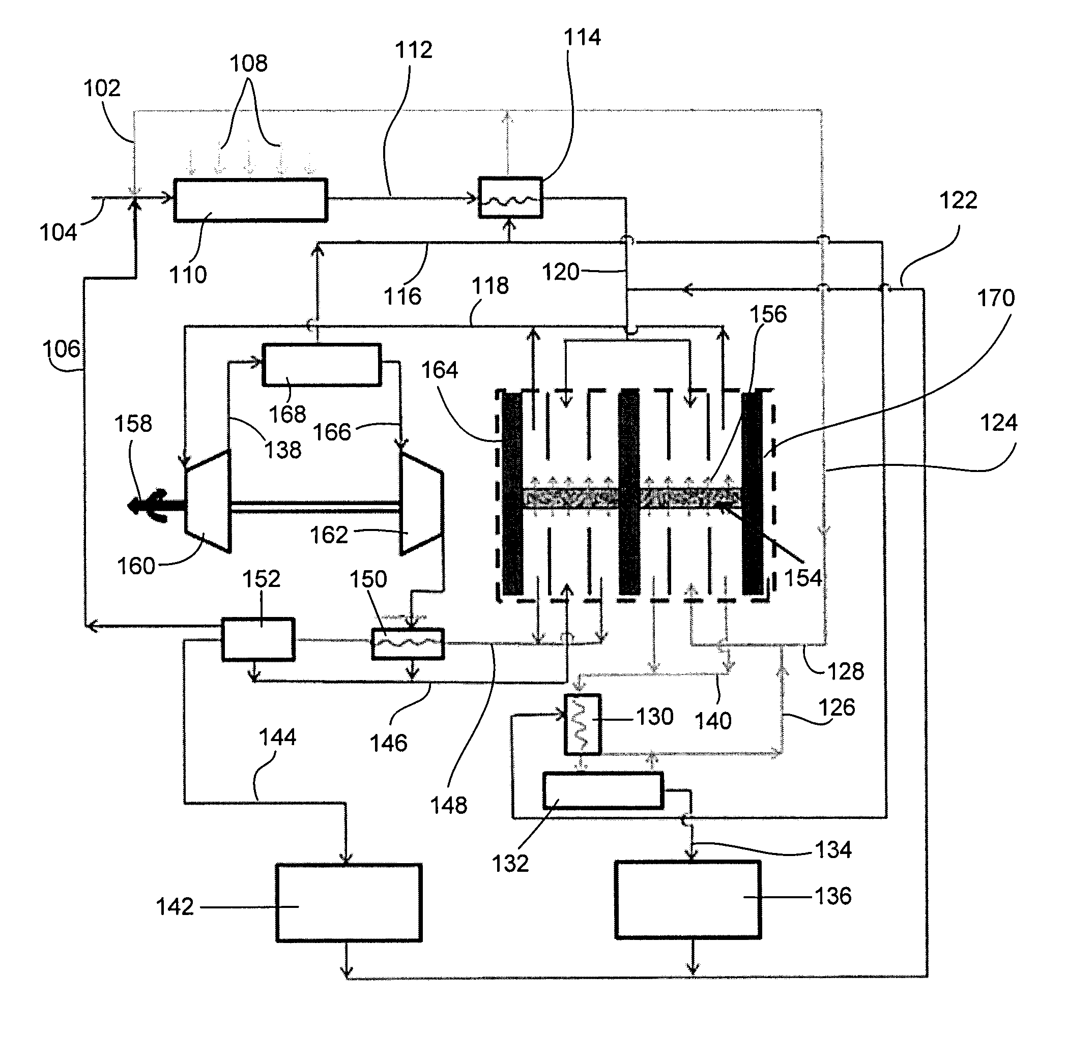
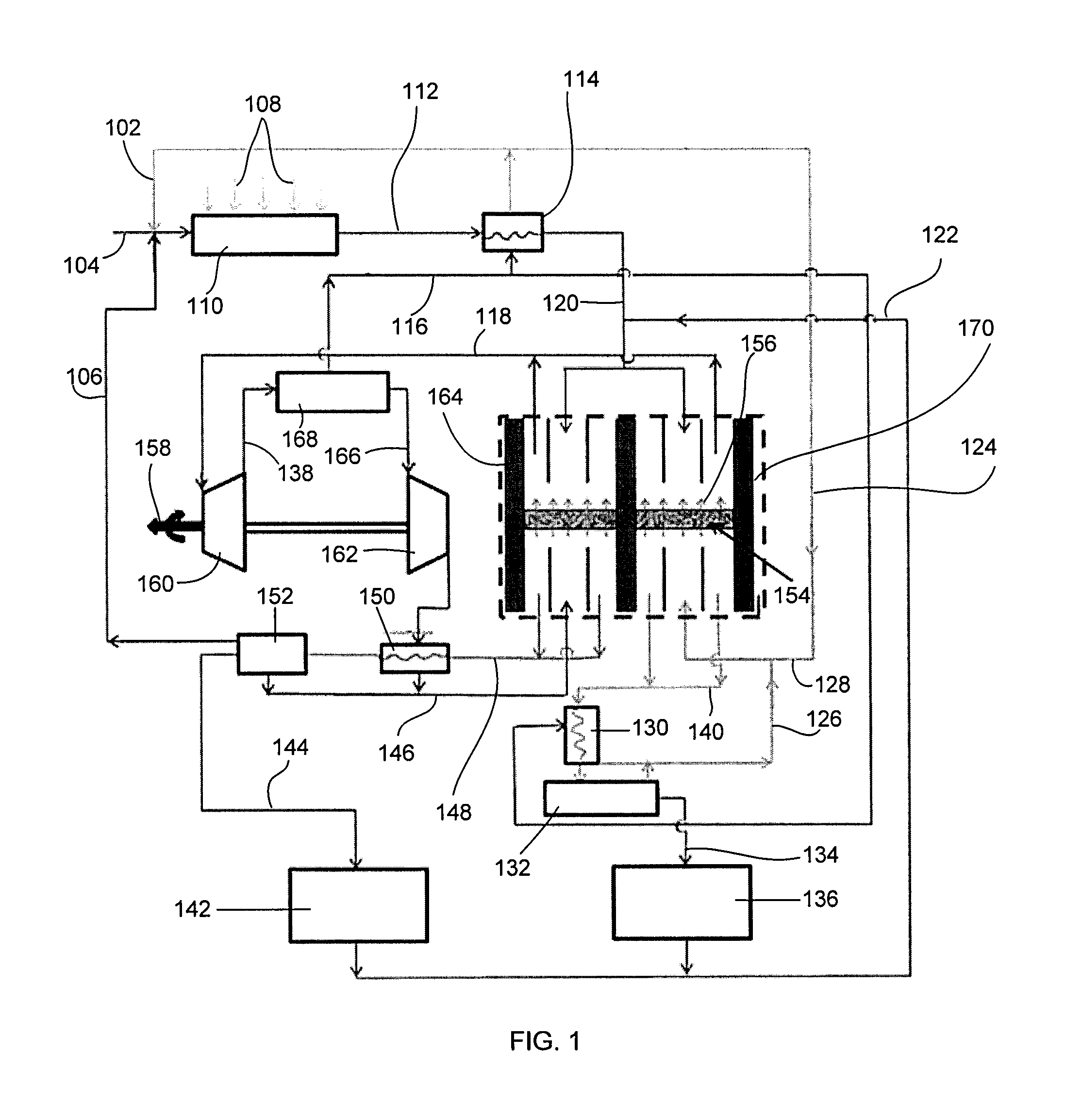
[0031]The present disclosure describes a design for a power cycle utilizing a gas turbine operated by the combustion gases from of an oxygen transport reactor (OTR). The OTR is used in the combustion process of syngas using the separated oxygen in the permeate side and in the splitting of H2O and CO2 for H2 and CO recovery, respectively. The combustion gases consist of H2O and CO2 which are fed again to the feed side in order to split H2 and CO, i.e. it is a closed-loop power cycle. Thus, a zero emission power cycle due to the complete exhaust gas recirculation from the permeate to the feed side of the membrane inside the OTR is disclosed. During the day time, the syngas production process is enhanced using a solar reformer which includes a method of reforming methane using H2O or CO2.

[0032]A zero-emission, closed-loop and hybrid solar-produced...


PUM


Abstract

A zero-emission, closed-loop and hybrid solar-produced syngas power cycle is introduced utilizing an oxygen transport reactor (OTR). The fuel is syngas produced within the cycle. The separated oxygen inside the OTR through the ion transport membrane (ITM) is used in the syngas-oxygen combustion process in the permeate side of the OTR. The combustion products in the permeate side of the OTR are CO2 and H2O. The combustion gases are used in a turbine for power production and energy utilization then a condenser is used to separate H2O from CO2. CO2 is compressed to the feed side of the OTR. H2O is evaporated after separation from CO2 and fed to the feed side of the OTR.

Description

BACKGROUND OF THE INVENTION[0001]1. Technical Field[0002]The present invention relates to a hybrid solar-syngas power cycle system comprising a solar reformer, a water evaporator, a plurality of oxygen transport membrane reactors, a plurality of condensers and a gas turbine in which the system is a zero emission fuel cycle and a method for producing syngas using the system in which the combustion products are used as feed gases in order to separate oxygen for combustion and produce syngas in the feed side of the oxygen transport membrane reactor.[0003]2. Description of the Related Art[0004]The “background” description provided herein is for the purpose of generally presenting the context of the disclosure. Work of the presently named inventors, to the extent it is described in this background section, as well as aspects of the description which may not otherwise qualify as prior art at the time of filing, are neither expressly or impliedly admitted as prior art against the present i...

Claims


Application Information

Patent Timeline
IPC IPC(8): F02C7/22B01J7/00F03G6/00C01B3/02F02C6/00F02C3/22
CPCF02C7/22F02C6/00F02C3/22F05D2220/32C01B3/02B01J7/00F03G6/00B01J12/007B01J2208/00451B01J2219/00144C01B3/34C01B13/0251C01B2203/0216C01B2203/0222C01B2203/0855C01B2203/0894C01B2203/1241C01B2203/84Y02E10/46Y02E60/36Y02P20/133Y02P30/00B01J10/007B01J19/2445B01J2219/24C01B3/042C01B3/506C01B13/0203C01B13/0207C01B2203/0205C01B2203/0495F02C1/05
Inventor NEMITALLAH, MEDHAT AHMEDHABIB, MOHAMED ABDEL-AZIZ
Owner KING FAHD UNIVERSITY OF PETROLEUM AND MINERALS
Why Eureka
Try Eureka