Semiconductor device
a semiconductor transistor and semiconductor technology, applied in the field of semiconductor devices, can solve the problems of difficult control of the threshold voltage of an oxide semiconductor transistor, variations in the characteristics of transistors, or a change in the threshold voltage of transistors, and achieve the effects of low power consumption, stable control, and high speed operation
- Summary
- Abstract
- Description
- Claims
- Application Information
AI Technical Summary
Benefits of technology
Problems solved by technology
Method used
Image
Examples
embodiment 1
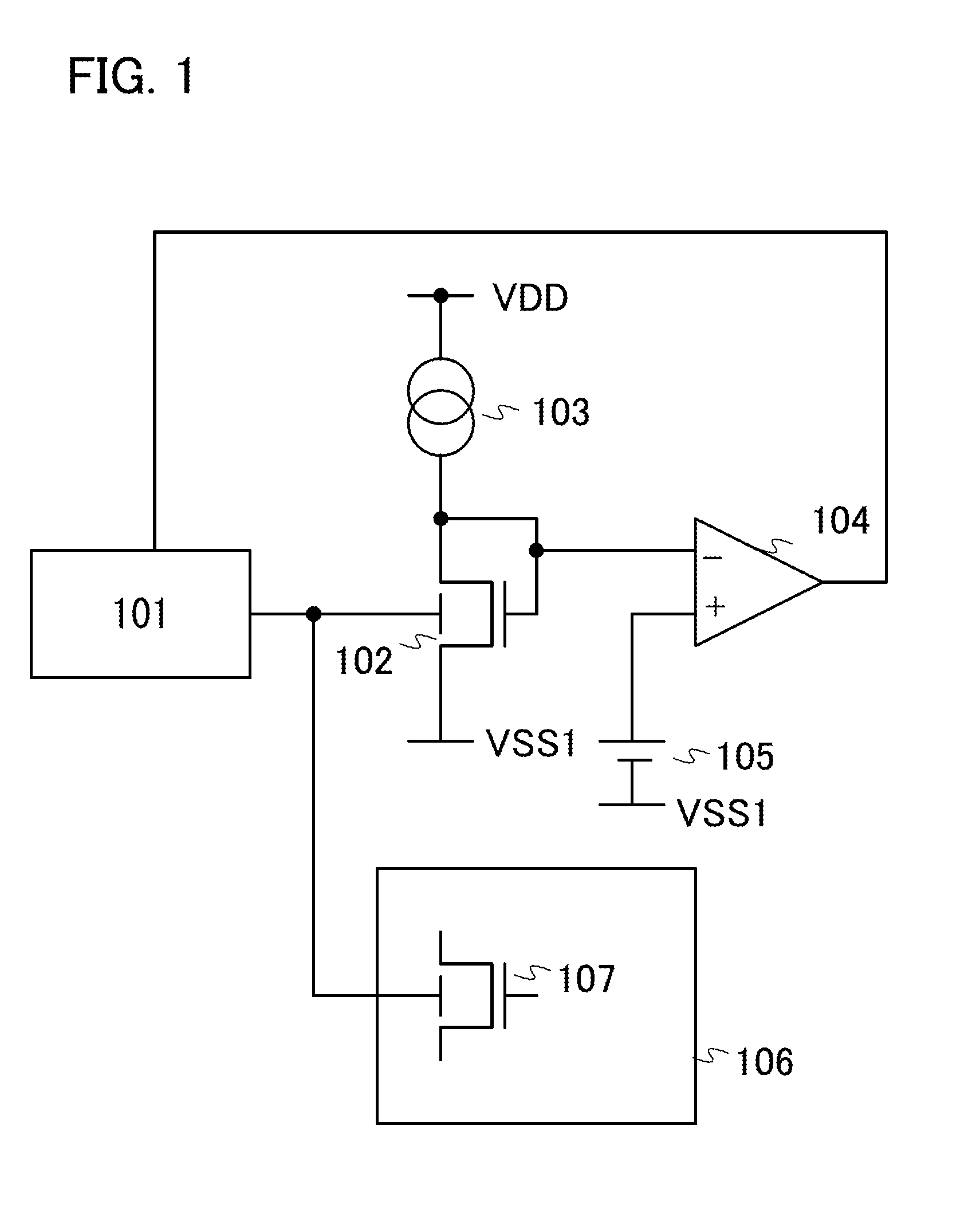
[0035]FIG. 1 is a block diagram of a semiconductor device of one embodiment of the present invention. The semiconductor device of one embodiment of the present invention includes a variable bias circuit 101, a transistor 102 for monitoring a threshold voltage, a current source 103, a differential amplifier 104, a reference voltage source 105, a functional circuit 106 using an oxide semiconductor, and an oxide semiconductor transistor 107. Here, the functional circuit 106 is a circuit which includes the oxide semiconductor transistor 107 having a controlled back gate, and is generally a memory, an arithmetic circuit, an amplifier circuit, or the like; however, one embodiment of the present invention is not limited thereto.
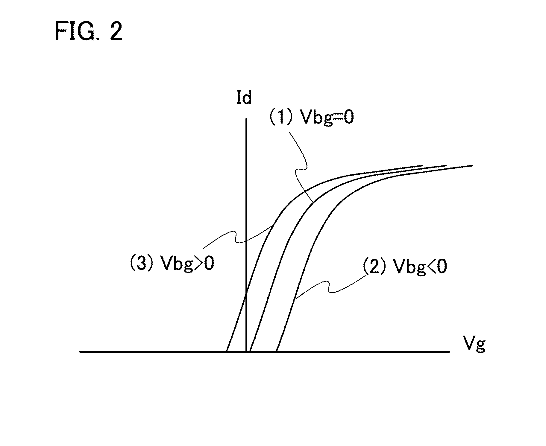
[0036]Components will be described below. The variable bias circuit 101 is a voltage-controlled voltage source which is controlled by an input voltage and generates voltage to be applied to a back gate (back gate control voltage Vbg). The transistor 102 for monitori...
embodiment 2
[0040]FIG. 3 is a more specific block diagram of the variable bias circuit 101. The variable bias circuit illustrated in FIG. 3 includes a PWM wave generation circuit 301, a constant voltage circuit 302, an inverter 303, level shifters 304 and 305, switch transistors 306 and 307, a resistor 308, and a capacitor 309. The PWM wave generation circuit 301 is a signal generation circuit capable of controlling a duty ratio in accordance with an input voltage.
[0041]The PWM wave generation circuit 301 is controlled by the output voltage of the differential amplifier 104; when the output voltage of the differential amplifier 104 is increased, a period during which the output of the PWM wave generation circuit 301 is at a high level is short, and when the output voltage of the differential amplifier 104 is decreased, a period during which the output of the PWM wave generation circuit 301 is at a low level is short. The output of the PWM wave generation circuit 301 is connected to a gate of th...
embodiment 3
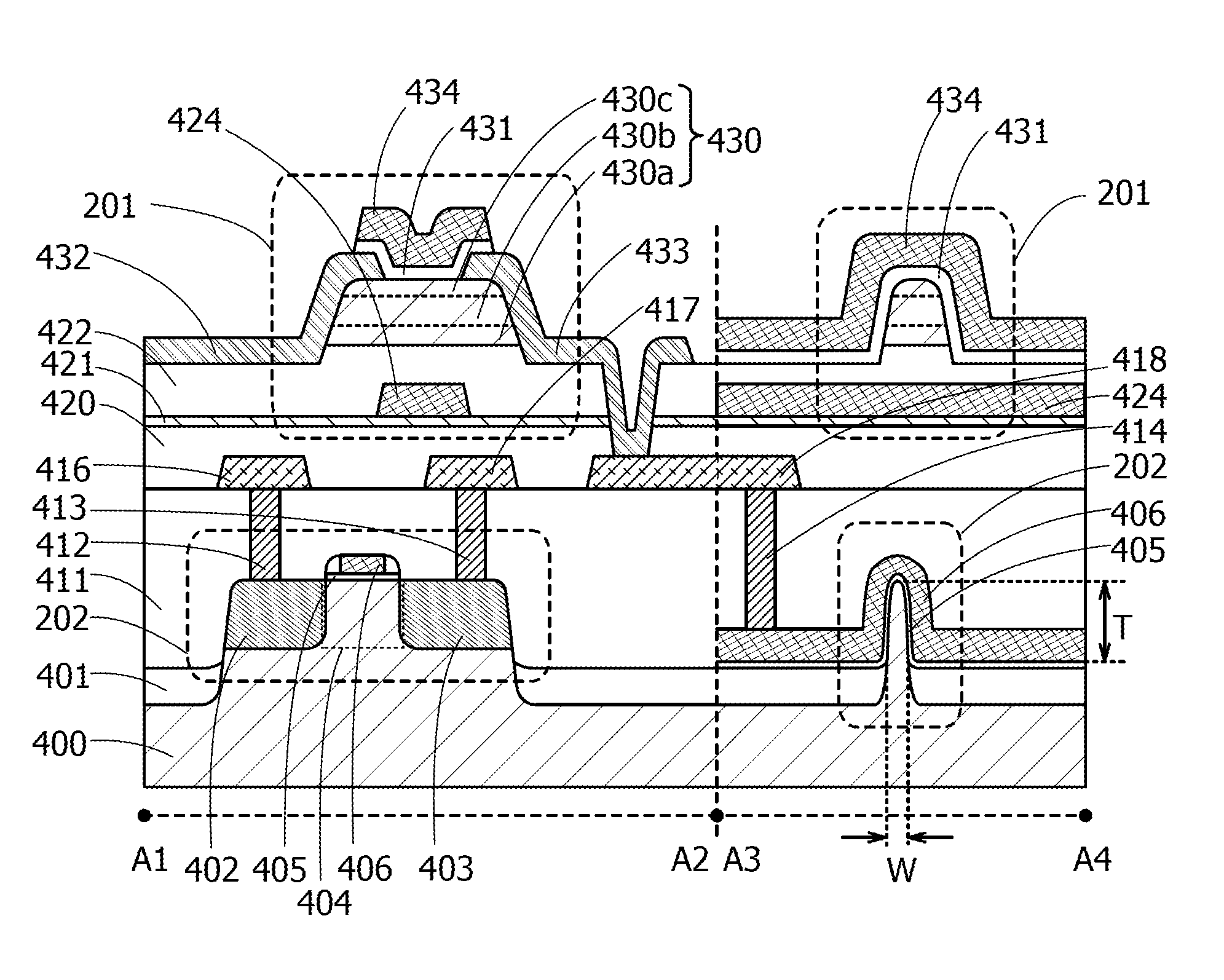
[0047]FIG. 6 shows an example in which an oxide semiconductor transistor is used for a memory circuit. The memory cell 200 includes a write transistor 201, a read transistor 202, and a storage capacitor 203. The case where the write transistor 201 is an oxide semiconductor transistor and the read transistor 202 is a p-channel Si transistor is described. The read transistor 202 may be an n-channel Si transistor or an oxide semiconductor transistor. Note that the memory circuit in this embodiment corresponds to the functional circuit 106 in the above embodiment, and the write transistor 201 corresponds to the oxide semiconductor transistor 107 described in the above embodiment.
[0048]A gate of the write transistor 201 is connected to a word line 204, and one of a source and a drain of the write transistor 201 is connected to a gate of the read transistor 202 and one electrode of the storage capacitor 203. The other electrode of the storage capacitor 203 is connected to a capacitor word...
PUM
 Abstract
Description
Claims
Application Information
 - R&D
- Intellectual Property
- Life Sciences
- Materials
- Tech Scout
- Unparalleled Data Quality
- Higher Quality Content
- 60% Fewer Hallucinations
Browse by: Latest US Patents, China's latest patents, Technical Efficacy Thesaurus, Application Domain, Technology Topic, Popular Technical Reports.
© 2025 PatSnap. All rights reserved.Legal|Privacy policy|Modern Slavery Act Transparency Statement|Sitemap|About US| Contact US: help@patsnap.com


