Integrated Photonic Coupler

a photonic integrated circuit and coupler technology, applied in the direction of instruments, optical waveguide light guides, optical light guides, etc., can solve the problems of difficult radiation coupling between optical fibers and photonic integrated circuits, such as planar photonic circuits using silicon technology, and the operational bandwidth of such couplers may be relatively limited, so as to achieve efficient radiation coupling and good coupling

Active Publication Date: 2015-10-08
INTERUNIVERSITAIR MICRO ELECTRONICS CENT (IMEC VZW) +1
View PDF12 Cites 15 Cited by
  • Summary
  • Abstract
  • Description
  • Claims
  • Application Information

AI Technical Summary

Benefits of technology

[0008]It is an object of embodiments of the present invention to provide efficient and good coupling of radiation into and out of an integrated photonic device, e.g., between an optical fiber and an integrated photonic device.
[0009]It is an advantage of embodiments according to the present invention that a high operating bandwidth can be achieved in a photonic coupler.
[0010]It is an advantage of embodiments according to the present invention that an integrated photonic coupler can be provided which is tolerant to fabrication imperfections.

Problems solved by technology

Coupling radiation between an optical fiber and a photonic integrated circuit, such as a planar photonic circuit using silicon technology, can be challenging for several reasons.
Three important challenges in light-chip coupling are achieving a good coupling efficiency between an optical fiber and the integrated circuit, achieving a high bandwidth, and dealing with implementation complexity.
However, despite the practical advantages of state-of-the-art grating couplers, the operational bandwidth offered by such couplers may be relatively limited, and the coupler may be sensitive to input polarization.
Furthermore, difficulties in achieving good fabrication tolerances in such couplers may also make them less attractive for industrial application.
However, the coupling efficiency of such coupler may be limited by the directional nature of diffraction, which furthermore can be improved to some extent by adding a substrate mirror.

Method used


Image

  • Integrated Photonic Coupler
  • Integrated Photonic Coupler
  • Integrated Photonic Coupler

Examples


Embodiment Construction

[0050]The present invention will be described with respect to particular embodiments and with reference to certain drawings but the invention is not limited thereto but only by the claims. The drawings described are only schematic and are non-limiting. In the drawings, the size of some of the elements may be exaggerated and not drawn on scale for illustrative purposes. The dimensions and the relative dimensions do not correspond to actual reductions to practice of the invention.

[0051]Furthermore, the terms first, second and the like in the description and in the claims, are used for distinguishing between similar elements and not necessarily for describing a sequence, either temporally, spatially, in ranking or in any other manner. It is to be understood that the terms so used are interchangeable under appropriate circumstances and that the embodiments of the invention described herein are capable of operation in other sequences than described or illustrated herein.

[0052]Moreover, t...


PUM


Abstract

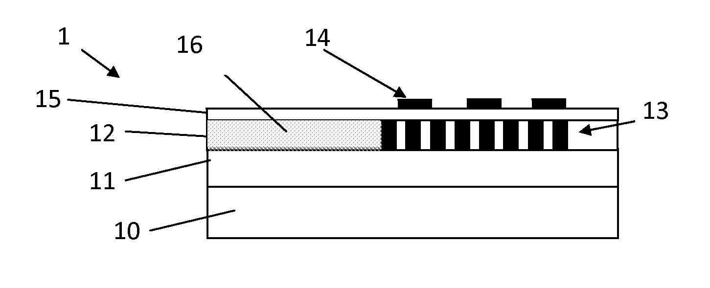
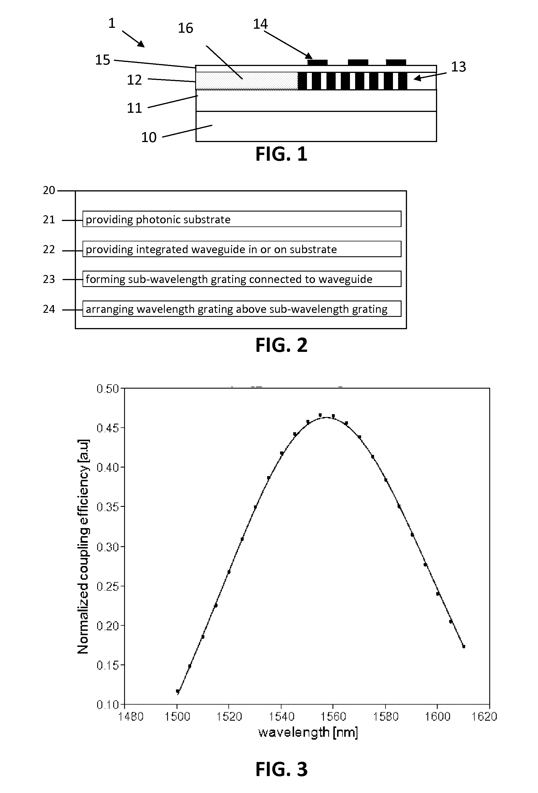
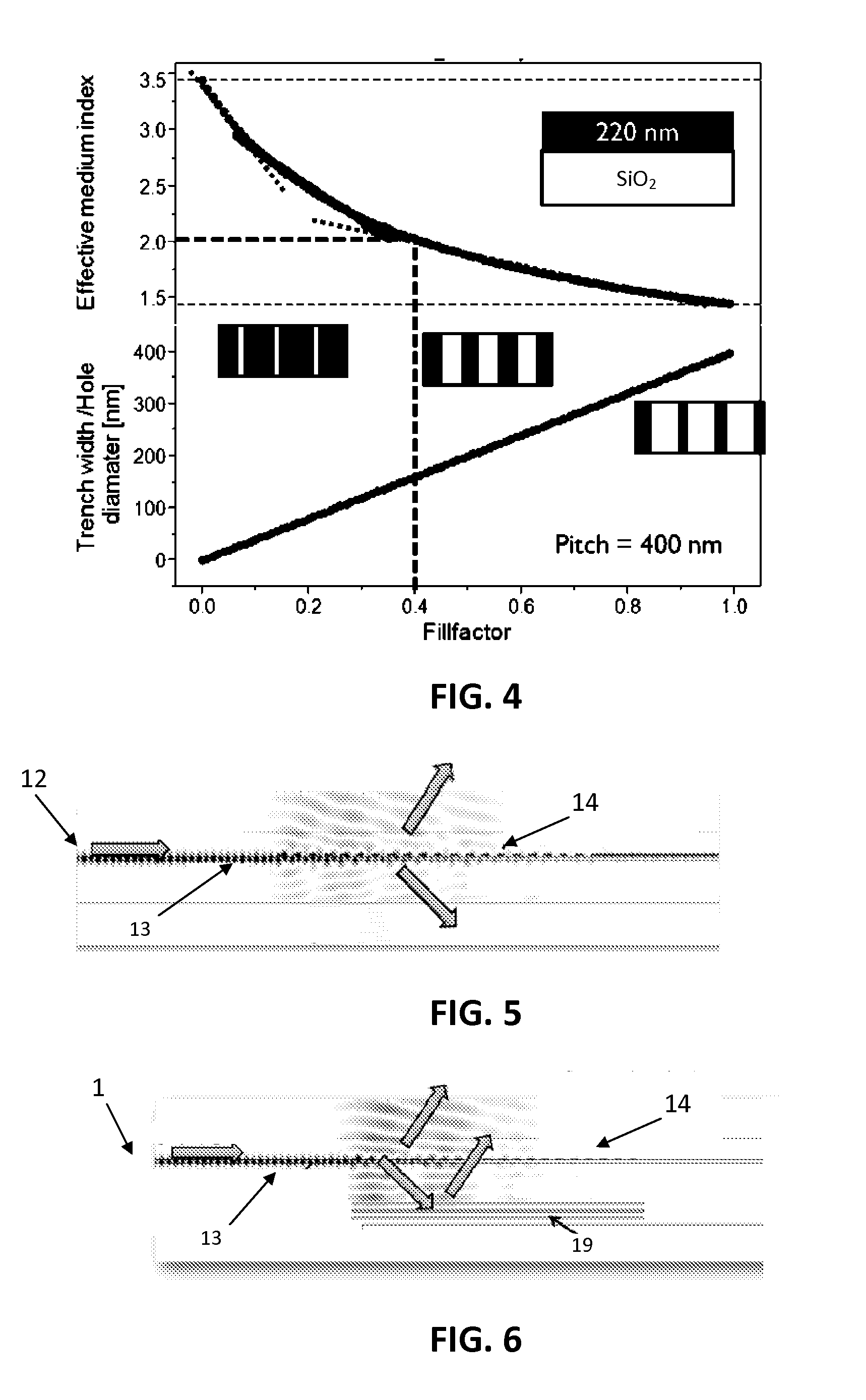
The present invention relates to an integrated photonic device comprising a photonic substrate, and an integrated waveguide provided in or on this substrate. The waveguide is adapted for conducting radiation of a predetermined wavelength. The device further comprises a sub-wavelength grating optically connected to the waveguide, which provides a first periodic variation of the refractive index in at least one first spatial direction. The device also comprises a diffracting grating arranged over the sub-wavelength grating for coupling radiation of the predetermined wavelength in and / or out of the integrated waveguide via the sub-wavelength grating. The diffracting grating provides a second periodic variation of the refractive index in at least one second spatial direction. The first periodic variation has a first pitch that is less than half of the predetermined wavelength, while the second periodic variation has a second pitch that is at least half of the predetermined wavelength.

Description

CROSS-REFERENCE TO RELATED APPLICATION[0001]Priority is claimed to European patent application 13199256.2 filed on Dec. 20, 2013, the contents of which are hereby incorporated by reference.FIELD OF THE INVENTION[0002]The invention relates to the field of photonic integrated circuits. More specifically it relates to systems and methods for coupling radiation between a chip and an optical fiber.BACKGROUND OF THE INVENTION[0003]Coupling radiation between an optical fiber and a photonic integrated circuit, such as a planar photonic circuit using silicon technology, can be challenging for several reasons. Three important challenges in light-chip coupling are achieving a good coupling efficiency between an optical fiber and the integrated circuit, achieving a high bandwidth, and dealing with implementation complexity.[0004]Grating-based fiber-chip couplers may provide a versatile solution which is relatively simple to implement and allows wafer-scale optical testing. Various advantages of...

Claims


Application Information

Patent Timeline
Patent Type & Authority Applications(United States)
IPC IPC(8): G02B6/124G02B6/136
CPCG02B6/124G02B2006/12107G02B2006/12176G02B6/136G02B6/30
Inventor SELVARAJA, SHANKAR KUMAR
Owner INTERUNIVERSITAIR MICRO ELECTRONICS CENT (IMEC VZW)
Why Eureka
Try Eureka