Plasma reactor for abating hazardous material

a plasma reactor and hazardous material technology, applied in the direction of machines/engines, separation processes, lighting and heating apparatus, etc., can solve the problems of reducing the decomposition rate of hazardous materials, affecting the operation of plasma reactors, and accumulating precursors between vacuum pumps and scrubbers. , to achieve the effect of reducing the decomposition rate, increasing the operation pressure, and increasing the durability of plasma reactors

Active Publication Date: 2015-10-29
KOREA INST OF MACHINERY & MATERIALS
View PDF0 Cites 3 Cited by
  • Summary
  • Abstract
  • Description
  • Claims
  • Application Information

AI Technical Summary

Benefits of technology

[0012]The present invention relates to a plasma reactor for decomposing and removing various hazardous materials in a front part of a vacuum pump, and to provide a plasma reactor for abating hazardous materials that enables a precursor decomposed by plasma, particle by-products, and fluorine radicals to not influence an insulator of the plasma reactor, thereby increasing durability and a decomposition rate of the hazardous materials.
[0013]In addition, the present invention provides a plasma reactor for an environmentally friendly process that increases the decomposition rate of greenhouse gases while guaranteeing safety of a process not using water vapor, and simplifies the entire system since it does not require additional equipment such as a bubbler.
[0024]The process gases may not flow through inside of the insulator. Accordingly, a decrease of decomposition rate of hazardous materials which occurs by a precursor decomposed by plasma being deposited on the insulator surface can be prevented, and durability of the plasma reactor can be increased by preventing a phenomenon in which a fluorine radical decomposed from greenhouse gases etches the insulator surface. In addition, when a third ground electrode is located in the first ground electrode, since it is possible to generate strong plasma at the center of the first ground electrode, the phenomenon that plasma density at the center area of the first ground electrode decreases as operation pressure increases can be suppressed, and the decomposition rate of hazardous materials is not decreased even when the operation voltage increases.
[0025]The plasma reactor is separately provided with an oxygen supply and a hydrogen (or hydrocarbon) source supply, two sorts of reaction gases are separately injected through two injection parts, and thereby the decomposition rate of hazardous substances included in the process gases can be effectively increased in comparison with the conventional art. In addition, safety of a process can be secured since explosion is avoidable by having different dissociation times of oxygen and hydrogen (or a hydrocarbon).

Problems solved by technology

As a result, this may cause an explosion when being excessively expanded while expansion and shrinking are repeated.
In addition, the undecomposed precursor accumulated between the vacuum pump and the scrubber is exposed when replacing the vacuum pump, the scrubber, or pipe, and some of this may cause a fire while violently reacting with air.
However, in a case that the hazardous materials flow through the inside of the plasma reactor, problems have been reported that the precursor decomposed by plasma is deposited on a insulator surface of the plasma reactor, or the particle by-products decomposed by plasma and fluorine radicals decomposed from the greenhouse gases etch the insulator surface.
A thickness increase of the insulator due to the deposition causes a decrease in decomposition rate of the hazardous materials, and the etching of the insulator causes insulation breakdown.
However, although the method of inputting the water vapor is good in terms of safety of the process, it has drawbacks that the decomposition rate of the greenhouse gases is low and the amounts of oxygen and hydrogen are unable to be individually controlled.
In addition, there is a technical difficulty in finely controlling the input of water vapor, and there is a limit that the entire system becomes complex since additional equipment such as a bubbler are required.

Method used


Image

  • Plasma reactor for abating hazardous material
  • Plasma reactor for abating hazardous material
  • Plasma reactor for abating hazardous material

Examples


Embodiment Construction

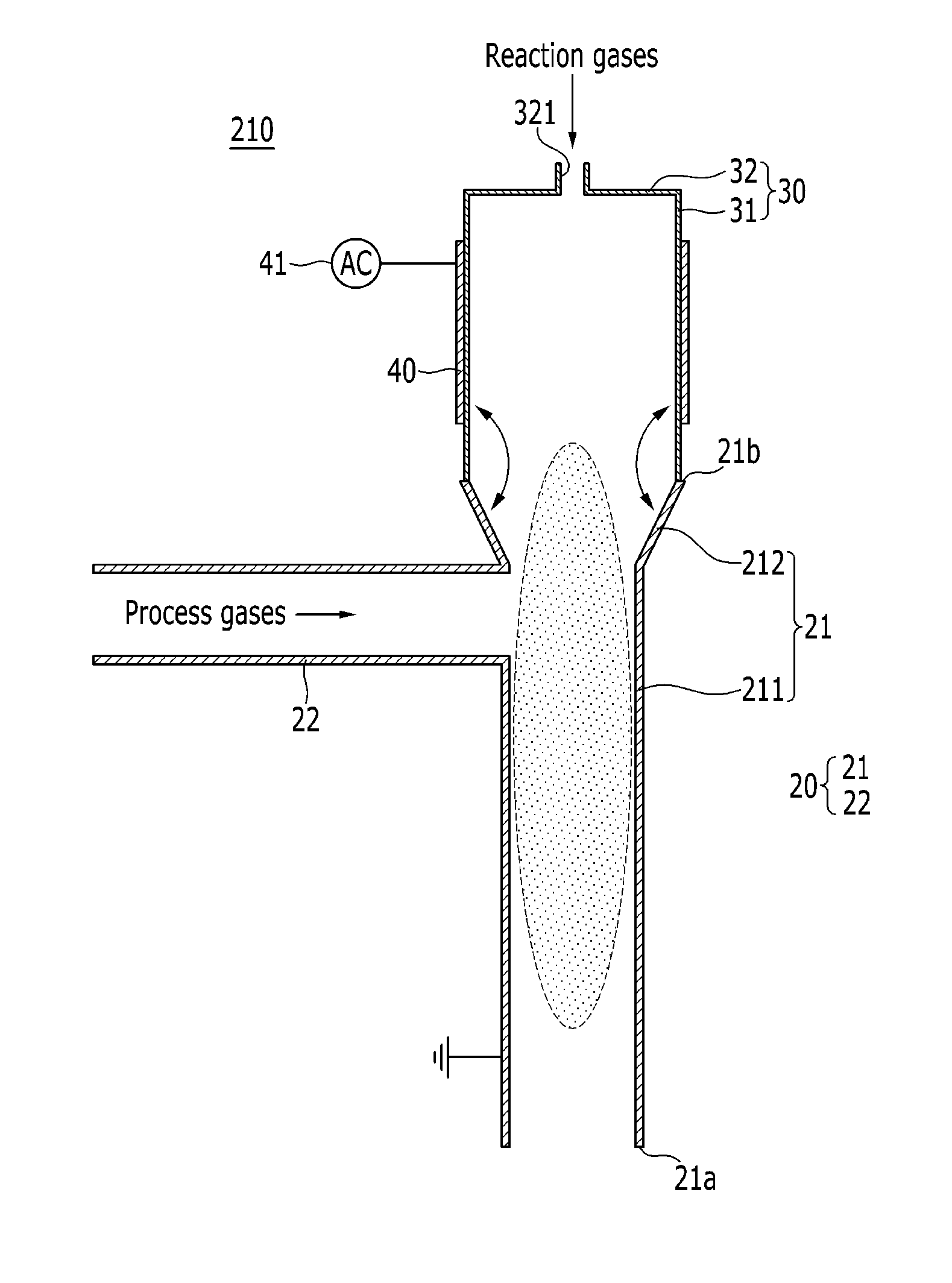
[0047]Hereinafter, the present invention will be described more fully hereinafter with reference to the accompanying drawings, in which exemplary embodiments of the invention are shown. The present invention may be implemented in various forms, and the scope of the present invention is not limited the embodiments described herein.

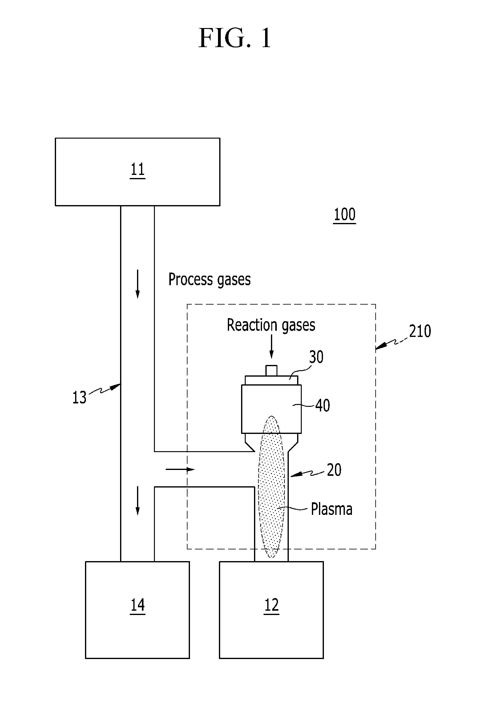
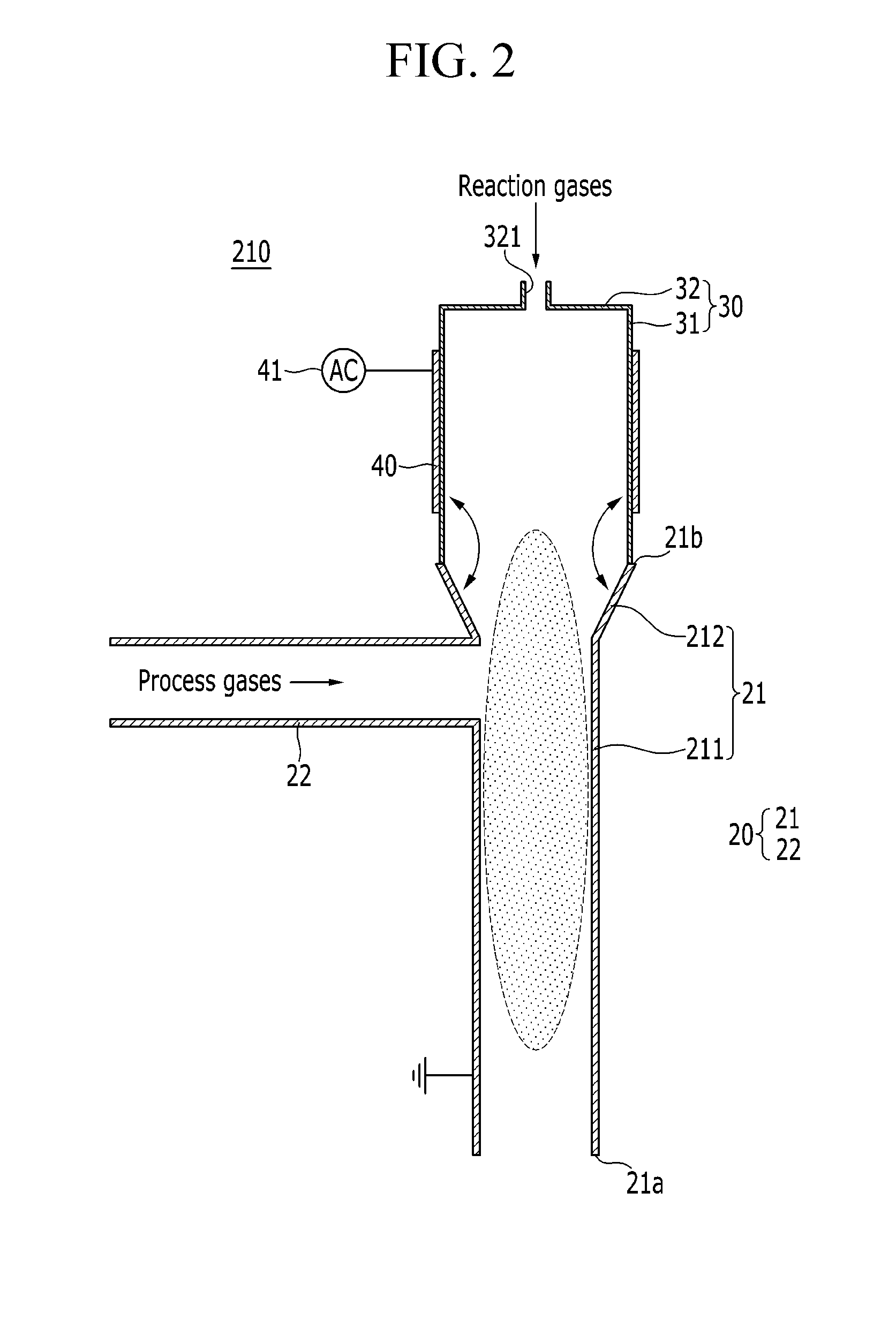
[0048]FIG. 1 is a schematic diagram of a process system including a plasma reactor according to the first exemplary embodiment of the present invention. The process system of FIG. 1 may be a low pressure process system for semiconductors, displays, solar cells, and so on.

[0049]Referring to FIG. 1, a process system 100 includes a process chamber 11 in which tasks such as etching, deposition, cleaning, etc. are processed, a vacuum pump 12 that discharges process gases of the process chamber 11, and a plasma reactor 210 connectedly installed on a pipe 13 between the process chamber 11 and the vacuum pump 12. The process system 100 is installed in parallel with...


PUM

PropertyMeasurementUnit
sizeaaaaaaaaaa
pressureaaaaaaaaaa
frequencyaaaaaaaaaa

Abstract

A plasma reactor for abating hazardous materials by decomposing various hazardous materials in a front end part of a vacuum pump is provided. A plasma reactor for abating hazardous materials includes a ground electrode part, an insulator, and a driving electrode. The ground electrode part includes a first ground electrode located in a front end part of the vacuum pump and having a tubular shape, including a first end part facing the vacuum pump and a second end part at an opposite side thereof, and a second ground electrode connected to a side of the first ground electrode and having a tubular shape and transferring the process gas. The insulator is connectedly installed to the second end part. The driving electrode is fixed to an outer surface of the insulator, a driving voltage is applied while being connected to a power supply, and low pressure plasma is generated inside of the first ground electrode due to a voltage difference from the ground electrode part.

Description

CROSS-REFERENCE TO RELATED APPLICATION[0001]This application claims priority to and the benefit of Korean Patent Application Nos. 10-2014-0051892 and 10-2014-0083093 filed in the Korean Intellectual Property Office on Apr. 29, 2014 and Jul. 3, 2014, the entire contents of which are incorporated herein by reference.BACKGROUND OF THE INVENTION[0002]1. (a) Field of the Invention[0003]The present invention relates to a plasma reactor, and more particularly, to a plasma reactor for attaining an environmentally friendly process by decomposing and removing various hazardous materials in a front end part of a vacuum pump.[0004]2. (b) Description of the Related Art[0005]A process chamber for performing processes such as etching, deposition, cleaning, and so on is installed in a manufacturing line of a semiconductor, a display, a solar cell, and the like, and the process chamber is connected to a vacuum pump to evacuate process gases. Various hazardous materials are discharged from the proces...

Claims


Application Information

Patent Timeline
Patent Type & Authority Applications(United States)
IPC IPC(8): B01D53/32
CPCB01D2259/818B01D53/323Y02C20/30B01D2257/204B01D2257/2066H05H1/246H05H1/2431H01J37/32
Inventor HUR, MINKANG, WOO SEOKLEE, JAE OK
Owner KOREA INST OF MACHINERY & MATERIALS
Why Eureka
Try Eureka