Wind turbine blades and method of manufacturing the same

a technology of wind turbine blades and wind turbine blades, which is applied in the direction of motors, applications, household objects, etc., can solve the problems of poor bonding between strips, failure of blades in use, and resin infusion,

Active Publication Date: 2015-11-05
VESTAS WIND SYST AS
View PDF2 Cites 22 Cited by
  • Summary
  • Abstract
  • Description
  • Claims
  • Application Information

AI Technical Summary

Benefits of technology

[0047]This method provides an efficient way of forming a strip in accordance with the invention in a continuous process. Shaping the die such that its cross section corresponds to the cross section of the strip of the invention means that no further manufacturing steps are required after the strip has been pultruded.
[0048]In one embodiment, the strip has peel p

Problems solved by technology

This lack of space makes it difficult for resin to infuse between the strips, and can result in a poor bond forming between the strips.
If the strips are not properly bonded together, then there is a risk of delamination occurring in the blade structure, which may lead to failure of

Method used


Image

  • Wind turbine blades and method of manufacturing the same
  • Wind turbine blades and method of manufacturing the same
  • Wind turbine blades and method of manufacturing the same

Examples


Embodiment Construction

[0055]A pultruded fibrous composite strip typically has a thickness of approximately 5 mm, and a peel ply layer typically has a thickness of approximately 50 to 500 microns. It will be appreciated that the drawings provided are not scale representations, and particular features of the strip have been greatly exaggerated for illustrative purposes.

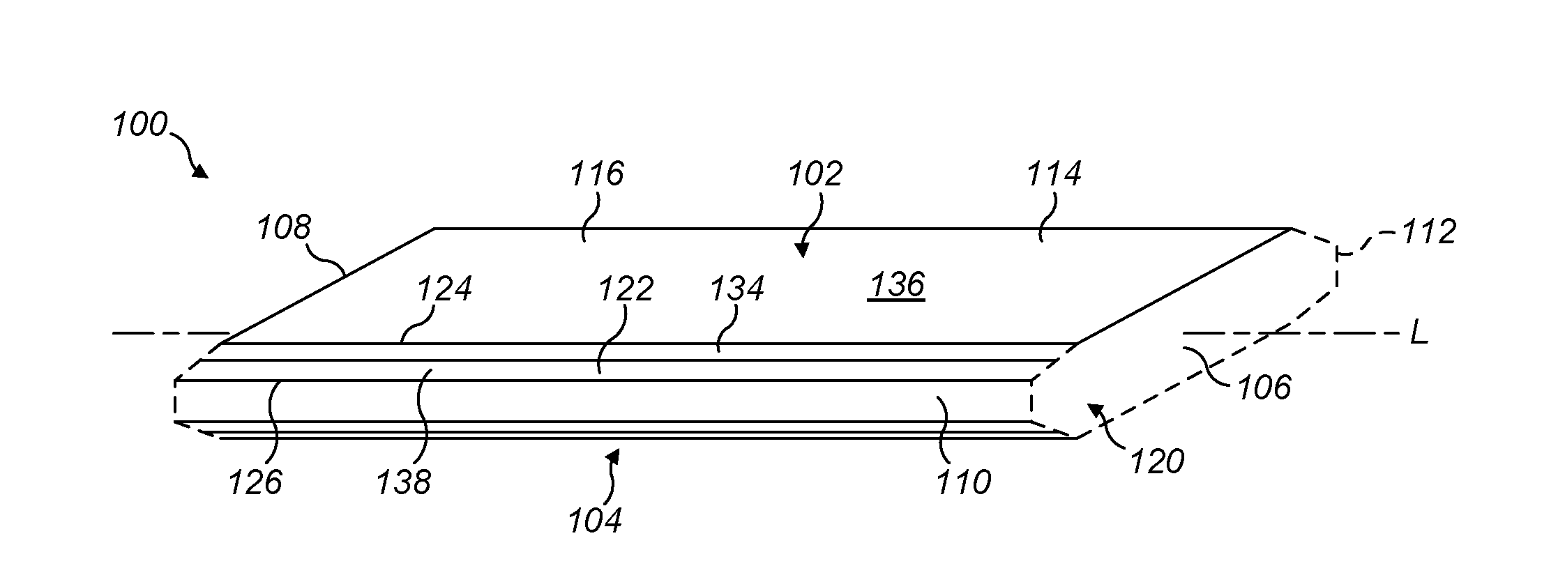
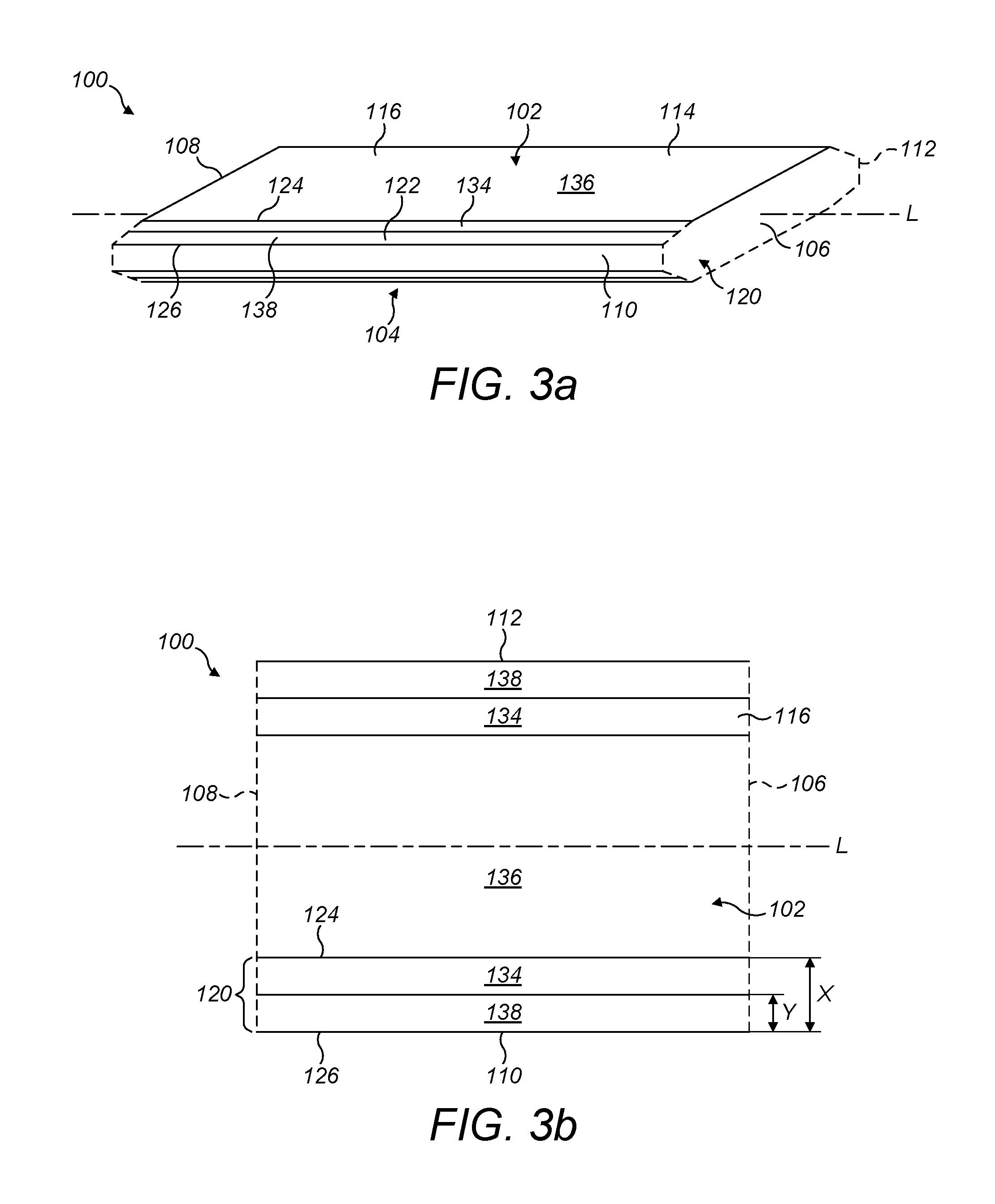
[0056]FIGS. 3a, 3b and 4a show a pultruded fibrous composite strip 100 for stacking with one or more similar strips to make a spar cap for a wind turbine blade. The strip 100 is made of a fibre-reinforced plastic, and comprises unidirectional carbon fibres aligned in a resin matrix.

[0057]The strip 100 is shaped substantially as a flat cuboid extending along a longitudinal axis L, the cuboid having a length substantially greater than its thickness or width. The strip 100 comprises first and second sides 102, 104 that extend longitudinally. The sides 102, 104 are joined by opposed transverse edges 106, 108 that are substantially perpendicular ...


PUM

PropertyMeasurementUnit
Thicknessaaaaaaaaaa

Abstract

Method of making a spar cap (146) for a wind turbine blade, the method comprising: (a) providing a plurality of elongate pultruded fibrous composite strips (100), each strip being of substantially constant cross section defined by first and second mutually opposed and longitudinally extending sides (102. 104) and by first and second longitudinal edges (110, 112), the first and second sides comprising, respectively, first and second planar abutment surfaces (118), the strip being of substantially uniform thickness between the first and second abutment surfaces, a first edge region (120) of the strip comprising a first edge of the strip being of relatively reduced thickness, the first side of the strip comprising an edge surface (122) adjacent the first abutment surface in the first edge region of the strip, and the strip having a first peel ply layer (114) at least partially covering the first abutment surface and at least partially covering the edge surface; (b) removing the first peel ply layers from the respective strips; (c) stacking the strips in a mould such that the first abutment surface of each strip abuts an abutment surface of an adjacent strip in the stack to define an interface region (142) between the strips, and such that a clearance region (144) is defined between the first edge region of each strip and an edge region of an adjacent strip in the stack; (d) supplying resin to the respective clearance regions and causing the resin to infiltrate into the interface regions between adjacent strips; and (e) curing the resin to bond the strips together.

Description

TECHNICAL FIELD[0001]The present invention relates generally to rotor blades for wind turbines and to methods of manufacturing wind turbine blades. More specifically, the present invention relates to wind turbine blades that include a stack of load-bearing reinforcing strips integrated within the structure of the shell, and to a method of making such blades.BACKGROUND[0002]FIG. 1 is a cross-sectional view of a wind turbine rotor blade 10. The blade 10 has an outer shell 12, which is fabricated from two half shells: a leeward shell 14 and a windward shell 16. The shells 14, 16 are moulded from glass-fibre reinforced plastic (GRP). Parts of the outer shell 12 are of sandwich panel construction and comprise a core 18 of lightweight foam (e.g. polyurethane), which is sandwiched between inner and outer GRP layers 20, 22 or ‘skins’.[0003]The blade 10 comprises first and second pairs of spar caps 24, 26, 28, 30 arranged between sandwich panel regions of the outer shell 12. One spar cap of ...

Claims


Application Information

Patent Timeline
IPC IPC(8): F03D1/06B32B3/26B32B3/02F03D1/00
CPCF03D1/0675F03D1/001B32B3/263Y10T29/49339B32B2603/00Y10T428/24488B32B3/02B29C70/52B29C70/547B29D99/0028B29D99/0007F03D13/10Y02E10/72Y02P70/50B29C65/70B29C70/543B29C70/546
Inventor SANDERCOCK, STEPHEN
Owner VESTAS WIND SYST AS
Why Eureka
Try Eureka