Wiring of assemblies and methods of forming channels in wiring assemblies

a technology of wiring assemblies and wiring assemblies, which is applied in the direction of superconducting magnets/coils, magnetic bodies, superconductor devices, etc., can solve the problems of beam loss within the system, performance of beam optics, rapid increase in beam cross sections, etc., and achieve uniform channel width and uniform width

Active Publication Date: 2015-11-05
ADVANCED MAGNET LAB
View PDF0 Cites 7 Cited by
  • Summary
  • Abstract
  • Description
  • Claims
  • Application Information

AI Technical Summary

Benefits of technology

[0070]According to a method of forming a channel with a restricted opening that secures multiple layers of conductor in a single channel, a channel is formed in a spiral configuration comprising a series of channel turns with the channel having a restricted opening of a first dimension smaller than a thickness dimension of the conductor by providing a first cut to a body to create a first width for an opening in the channel through which portions of the conductor are received into the channel. The thickness dimension may be the smallest dimension of the conductor. A second cut is made to create a second width in the channel larger than the first width. The first cut and the second cut may each be created with a tool and each may be created with a different tool. The first cut may create the majority of the depth of the channel to receive multiple layers of conductor with one layer stacked over another layer. Also, the first cut may provide a uniform width along a path defined by multiple ones of the channel turns, and the second cut may create a second width in the channel larger than the first width without altering the width of the opening.
[0071]In a method of forming a channel with a restricted opening a channel is formed which has a spiral configuration comprising a series of channel turns with the channel having a restricted opening of a first dimension smaller than a thickness dimension of the conductor by providing a first cut to a body to create an initial opening. At least a portion of the channel with the initial opening has a first width and a portion of the interior of the channel also has the first width. The initial opening is covered with a layer of removable material and a second cut creates the restricted opening through the layer of removable material. The restricted opening has the second width which is smaller than the first width. The first cut and the second cut may each be each created with a different tool, and the first cut may create the majority of the depth of the channel to receive multiple layers of conductor with one layer stacked over another layer. The first cut may provide a uniform channel width along a path defined by multiple ones of the channel turns, and the second cut may provide a uniform width to the restricted opening along a path defined by multiple ones of the channel turns.

Problems solved by technology

Any field errors (i.e., deviations from the ideal field strength distribution for a given application) in such systems are known to degrade the performance of the beam optics, leading to a rapid increase in beam cross sections, or beam loss within the system.
In the case of mass spectrometry, field uniformity is a limiting factor in the ability to separate particles of differing masses.
In these instances, the shapes of the iron poles which are magnetized with current-carrying windings are highly determinative of the field quality.
However, beam optics for high particle energy applications require very strong magnetic fields to control the particle beam.
For most of these machines, the iron-poles dominate the fields such that minor deviations in placement of coils in the winding configuration has little effect on machine performance.
For fully superconducting machines, non-uniform fields lead to increased AC losses in the windings, reducing machine efficiency.

Method used


Image

  • Wiring of assemblies and methods of forming channels in wiring assemblies
  • Wiring of assemblies and methods of forming channels in wiring assemblies
  • Wiring of assemblies and methods of forming channels in wiring assemblies

Examples


Embodiment Construction

[0132]Before describing in detail particular methods, structures and assemblies related to embodiments of the invention, it is noted that the present invention resides primarily in a novel and non-obvious combinations of components and process steps. So as not to obscure the disclosure with details that will be readily apparent to those skilled in the art, certain conventional components and steps have been omitted or presented with lesser detail, while the drawings and the specification describe in greater detail other elements and steps pertinent to understanding the invention. Further, the following embodiments do not define limits as to structure or method according to the invention, but only provide examples which include features that are permissive rather than mandatory and illustrative rather than exhaustive.

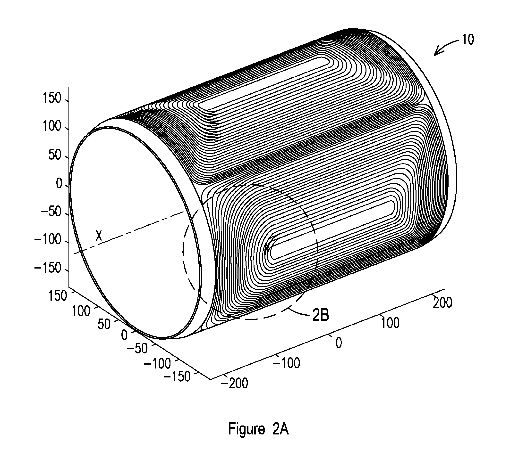
[0133]According to embodiments of the invention, the current density distribution in any cross section perpendicular to the central axis of symmetry of the coil system i...


PUM

PropertyMeasurementUnit
magnetic fieldsaaaaaaaaaa
angleaaaaaaaaaa
angleaaaaaaaaaa

Abstract

A conductor assembly and method for making an assembly of the type which, when conducting current, generates a magnetic field or which, in the presence of a changing magnetic field, induces a voltage. In one series of embodiments the assembly comprises a spiral configuration, positioned along paths in a series of concentric cylindrical planes, with a continuous series of connected turns, each turn including a first arc, a second arc and first and second straight segments connected to one another by the first arc. Each of the first and second straight segments in a turn is spaced apart from an adjacent straight segment in an adjoining turn.

Description

PRIORITY BASED ON RELATED APPLICATION[0001]This application claims priority from U.S. Provisional Application No. 61 / 734,116 filed Dec. 6, 2012. This application incorporates by reference all subject matter in U.S. Pat. No. 6,921,042 and U.S. Pat. No. 7,864,019.FIELD OF THE INVENTION[0002]This application relates to wiring assemblies and methods of forming wiring assemblies and systems including wiring assemblies which, when conducting current, generate a magnetic field or which, in the presence of a magnetic field, induce a voltage.BACKGROUND AND SUMMARY OF THE INVENTION[0003]Numerous magnet applications require provision of a magnetic field on the inside or the outside of a cylindrical structure with a varied number of magnetic poles. Examples of such applications are use of magnets for charged particle beam optics such as used in particle accelerator applications, particle storage rings, beam lines for the transport of charged particle beams from one location to another, and spec...

Claims


Application Information

Patent Timeline
Patent Type & Authority Applications(United States)
IPC IPC(8): H01F7/20H01F6/06H01F41/04
CPCH01F7/20H01F41/04Y10T29/49021H01F6/06Y10T29/49016H01F41/048H05H7/04H01F7/202H01F2041/0711H01F27/29B65H39/16
Inventor MEINKE, RAINERSHOULTZ, GREGORY J.STELZER, GERALD M.ROMANO, FERDINAND M.
Owner ADVANCED MAGNET LAB
Why Eureka
Try Eureka