

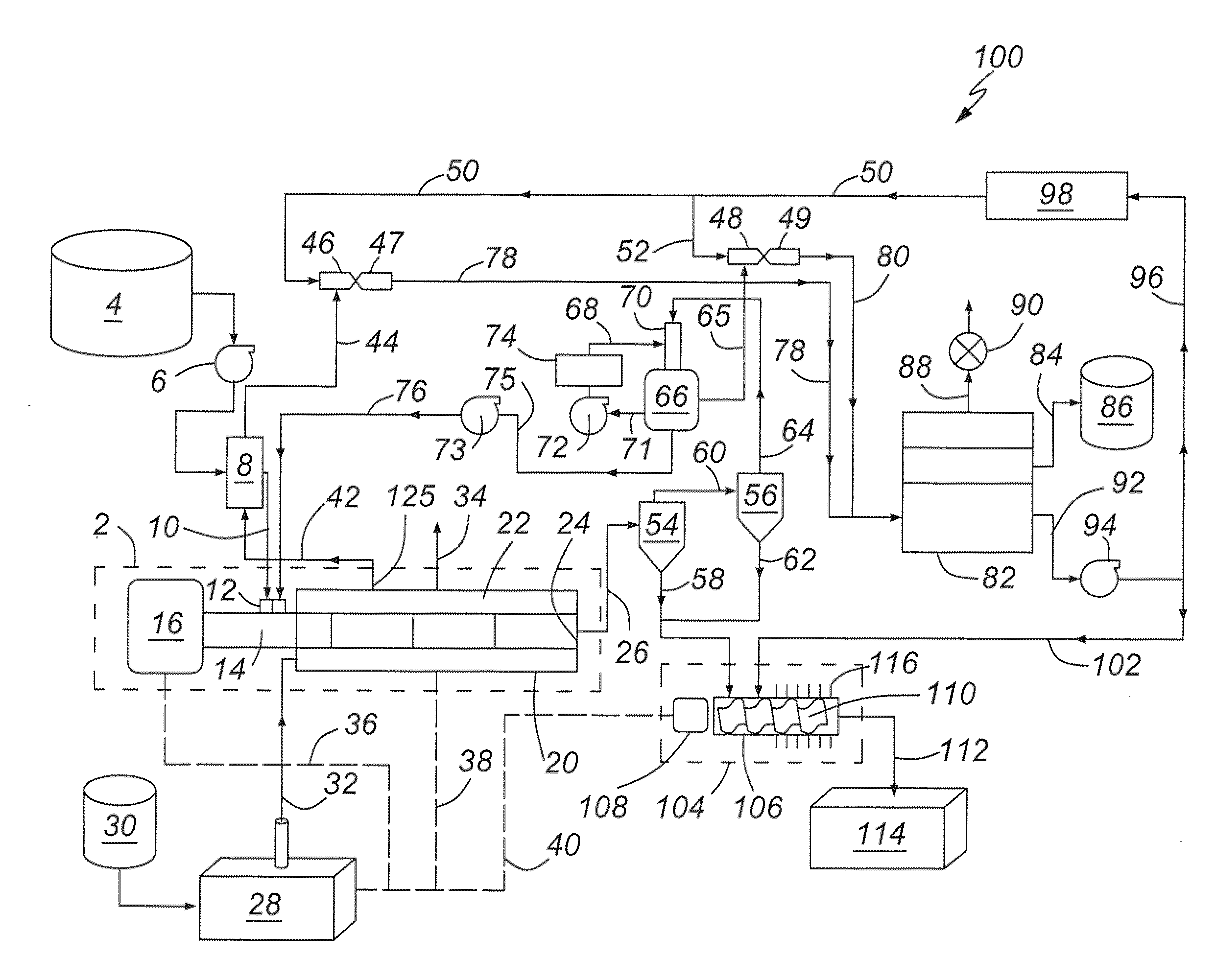
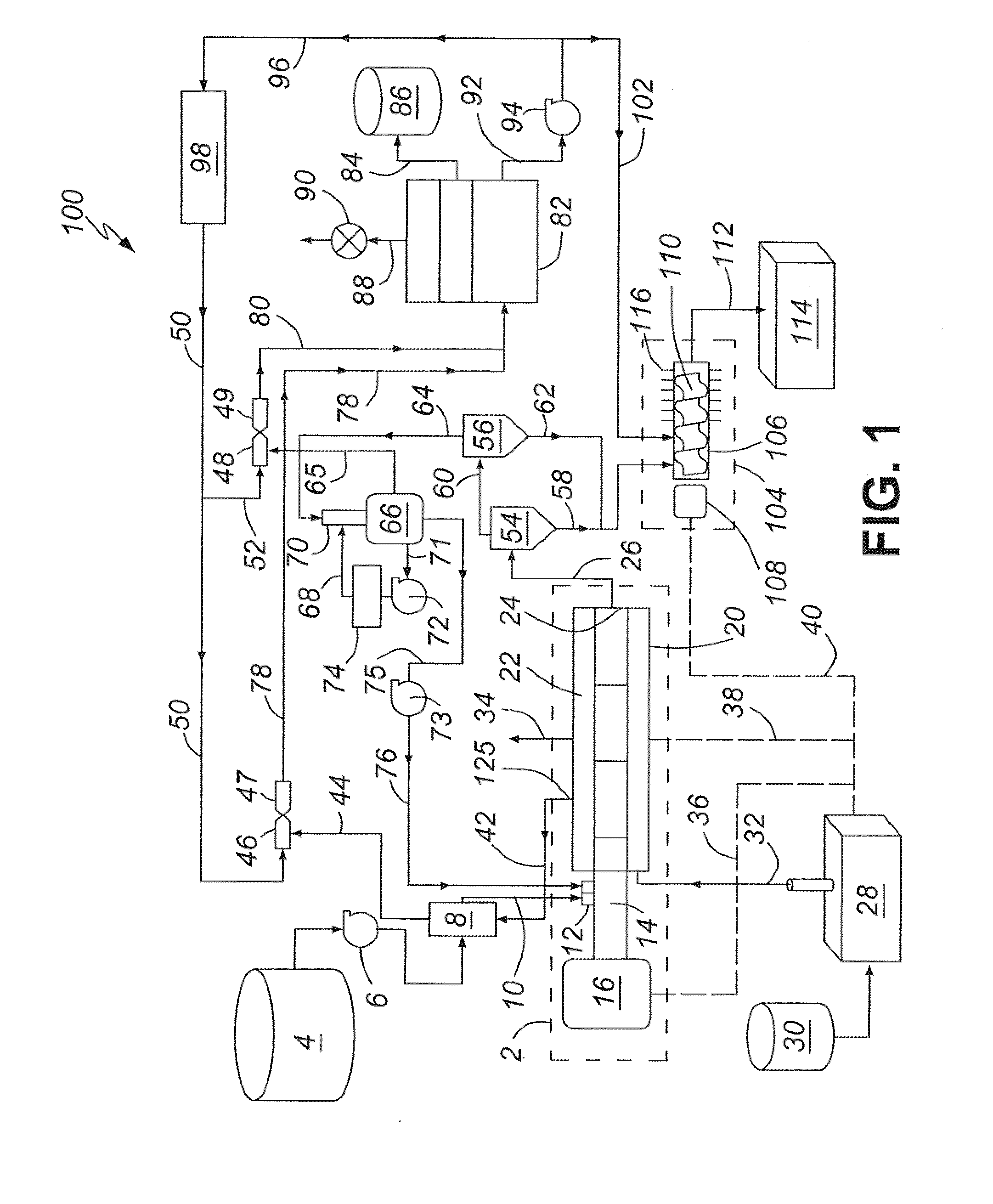
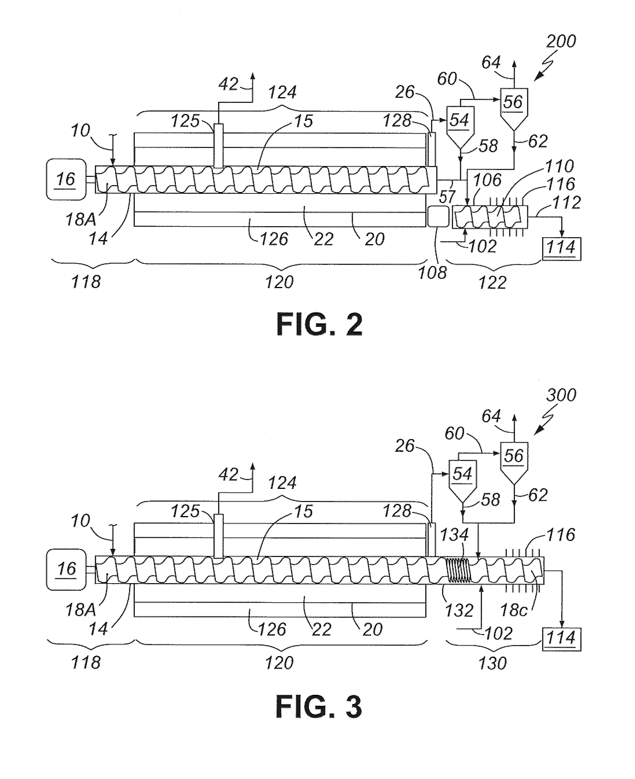
Turbulent vacuum thermal separation methods and systems
a vacuum thermal separation and vacuum technology, applied in the field of liquid/solid separation methods and systems, can solve the problems of inability to further extract hydrocarbons, inability to meet the needs of liquid hydrocarbon mixture production, etc., and achieve the effects of improving the efficiency of liquid hydrocarbon production
- Summary
- Abstract
- Description
- Claims
- Application Information
AI Technical Summary
Benefits of technology
Problems solved by technology
Method used
Image

Examples
examples
[0119]A series of tests were conducted using the pilot unit described herein to process a number of slurry feed compositions. Tests were conducted using both water, oil and oil / water based slurries. The solid particles included various clays including bentonite, barite, and calcium carbonate. Other organic chemicals were added to the slurry to ensure the solids remained suspended and thoroughly homogenized and stable, i.e. no separation, throughout the tests. Most slurries were non-Newtonian fluids. Table 3 lists the oil / water / solids content of slurries that were tested and for which a complete mass and energy balance was calculated. The slurries were successfully processed into dry solids comprising less than 1 dry weight percent oil content resulting in significant volume reduction. The recovered oil was of very high quality, which required no additional filtering or processing or treatment. The recovered water was also of very high quality and required only a simple oil / water sep...
PUM
 Abstract
Description
Claims
Application Information