Spin transfer torque magnetic memory device using magnetic resonance precession and the spin filtering effect

a magnetic memory and spin transfer torque technology, applied in the field of magnetic memory devices, can solve the problems of low critical current density, high integration limit of the device, and inability to write magnetic data, etc., to achieve the effect of reducing the critical current density, high degree of integration of the device, and reducing the need for critical current density

Active Publication Date: 2015-11-26
SAMSUNG ELECTRONICS CO LTD
View PDF6 Cites 6 Cited by
  • Summary
  • Abstract
  • Description
  • Claims
  • Application Information

AI Technical Summary

Benefits of technology

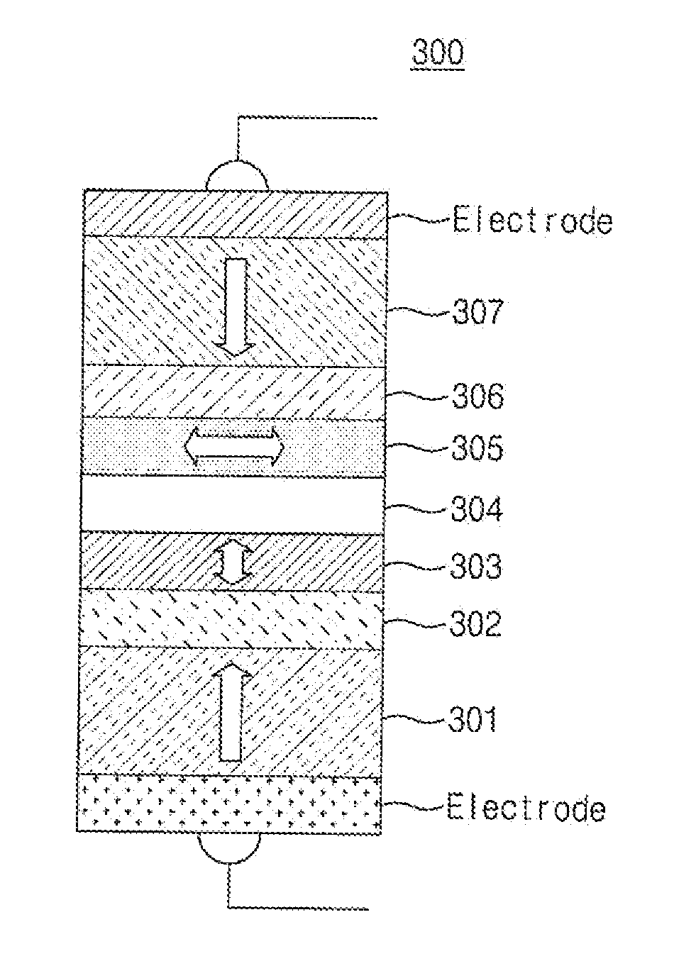
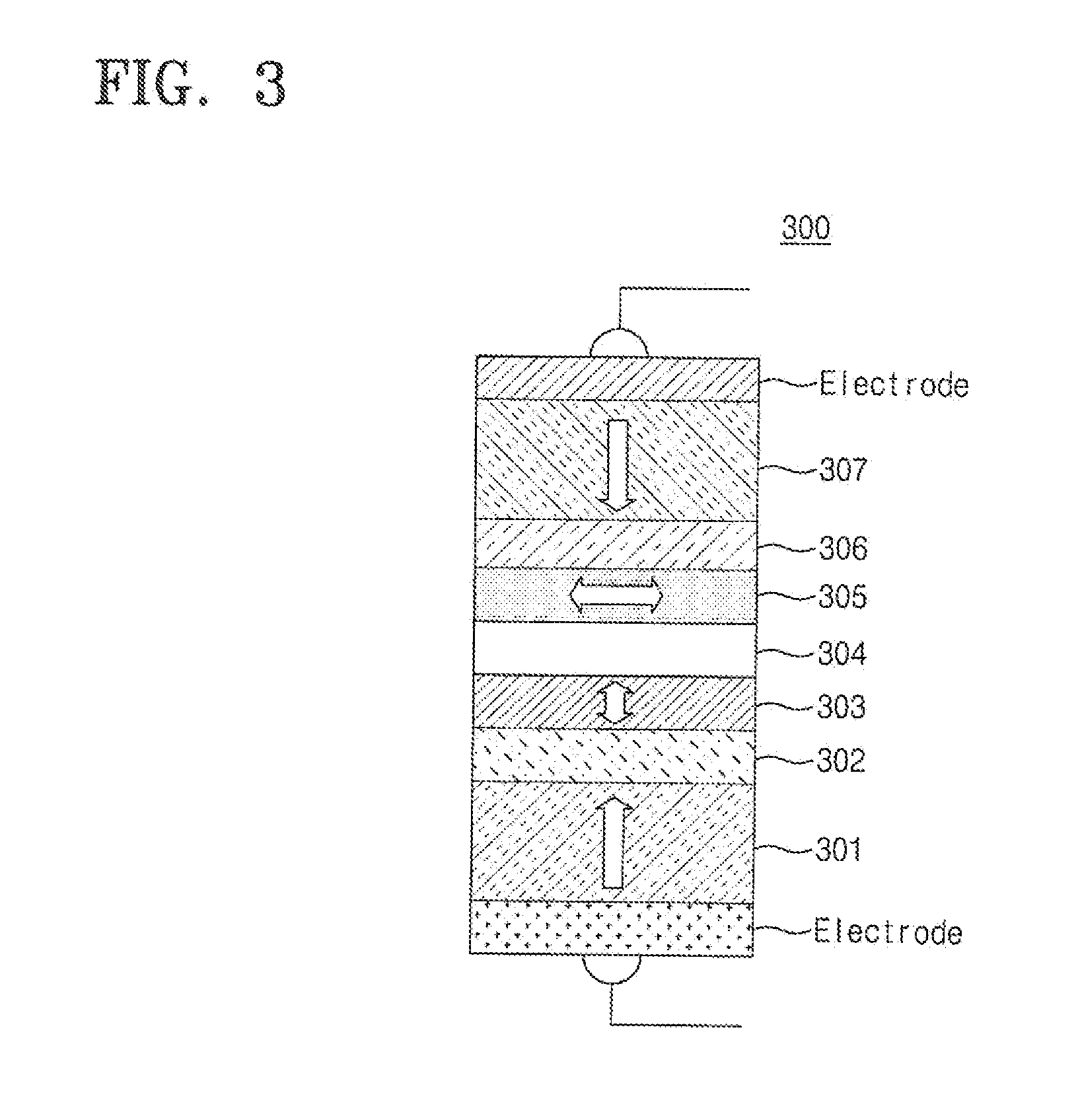
[0039]The magnetic memory device having a new structure according to the present invention further includes the free magnetic layer constituting a horizontal direction variable magnetization layer having a fixed saturation magnetization value, whereby a switching current is markedly reduced as compared with conventional magnetic layers such that a high degree of integration of the device can be achieved and it is possible to lower a critical current density necessary for magnetization reversal thereby reducing a power consumption of the device. Also, a stray field effect occurring from a fixed magnetic layer is reduced such that a written magnetization data is thermally stable.

Problems solved by technology

If an external magnetic field is used in order to control the magnetization of a free layer, a half-selected cell problem occurs with the reduction of a size of a device to limit high integration of the device.
This is a limitation of super-paramagnetism and causes a problem that a written magnetic data is undesirably erased.
In addition, because the amount of a current provided in a complementary metal-oxide-semiconductor (CMOS) transistor device is limited, a low critical current density for the magnetization reversal of the free magnetic layer is required.
However, the principle and the structure surely require an additional device for inducing the modulation magnetic field, and it was confirmed that a reduction effect of a driving power was less effective in an entire device.
Thus, characteristics of the device are deteriorated by the stray field generated from the first magnetic material.
Additionally, if the saturation magnetization value of a magnetic layer is 650 emu / cm3 or more, the influence of a corresponding magnetic layer on a neighboring magnetic layer increases to be likely to cause problems on characteristics of the device.

Method used


Image

  • Spin transfer torque magnetic memory device using magnetic resonance precession and the spin filtering effect
  • Spin transfer torque magnetic memory device using magnetic resonance precession and the spin filtering effect
  • Spin transfer torque magnetic memory device using magnetic resonance precession and the spin filtering effect

Examples


embodiment

[0075]The effect of the magnetic memory device according to the present invention was confirmed through micro-magnetic modeling using an equation of motion of magnetization. The justification of this method was efficiently secured through a conventional computer hard disk development and spin-transfer-torque research.

[0076]The equation of motion of the magnetization is expressed by the following equation 3.

∂m1∂t=-γ(m1×H2eff)+αm1×∂m1∂t-γℏη1je2eMS1d1m1×(m1×p1)+γℏjeη2→12eMS1d1m1×(m1×m2)∂m2∂t=-γ(m2×H2eff)+αm2×∂m2∂t-γℏη2je2eMSd2m2×(m2×m1)+γℏη3je2eMS2d2m1×(m1×p2)p1=z^,p2=z^[Equation3]

[0077]In the equation 3,

[0078]“m1” and “m2” denote unit magnetization vectors of the first free magnetic layer 203 and 303 and the second free magnetic layer 205 and 305, respectively, “γ” denotes a magnetic rotational constant, “H1eff” and “H2eff” denotes entire effective magnetic field vectors of the first free magnetic layer 203 and 303 and the second free magnetic layer 205 and 305, respectively, “α” deno...

experimental example 1

Magnetization Behavior of First Free Magnetic Layer and Second Free Magnetic Layer According to a Time Caused by Applying a Current to the Device According to the Present Invention

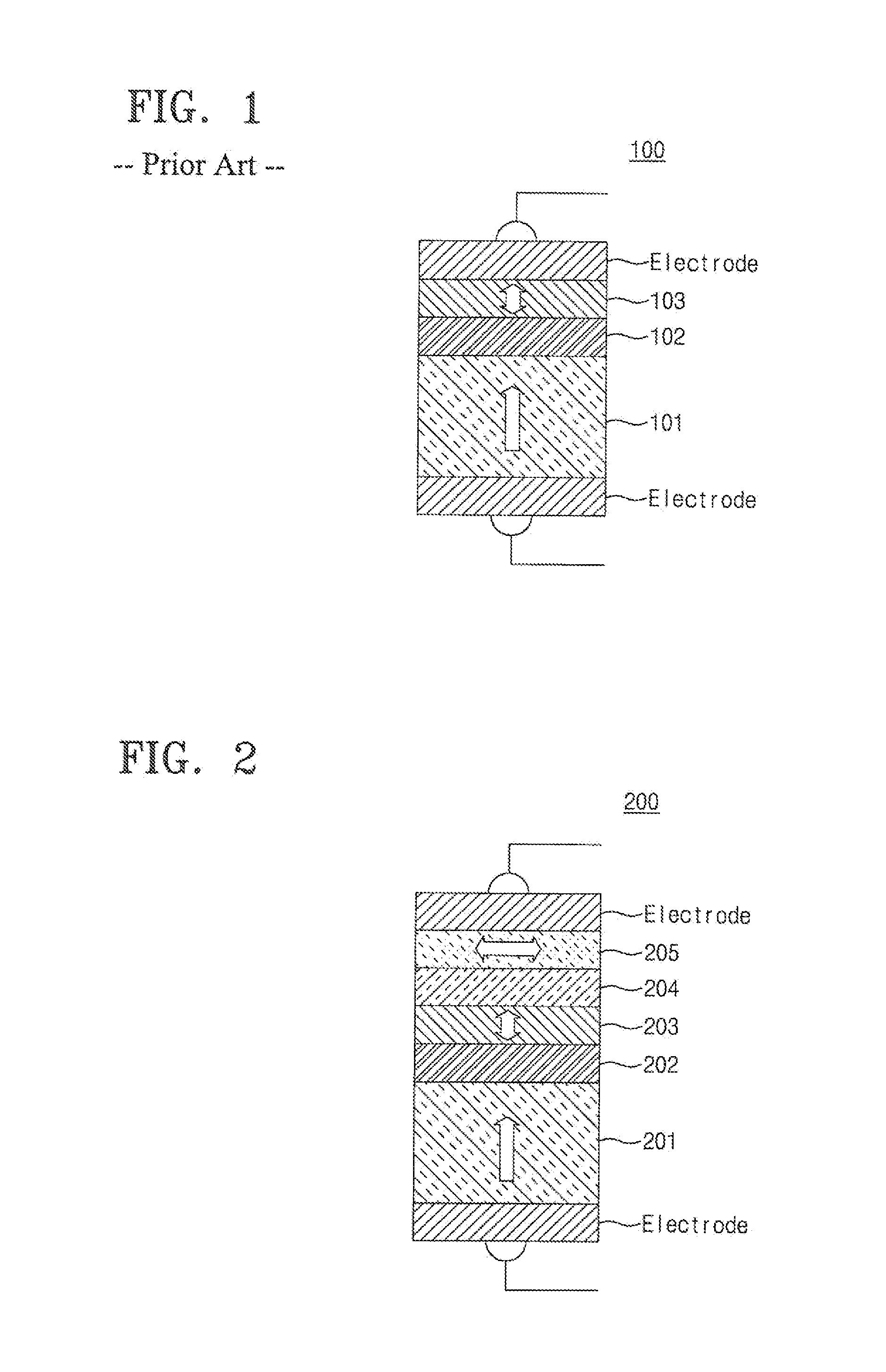
[0079](1) There is illustrated magnetization behavior of the first free magnetic layer having the perpendicular anisotropy and the second free magnetic layer having the horizontal anisotropy when the current is applied to the magnetic memory device according to an embodiment of the present invention as shown in the following FIG. 2.

[0080](2) Structure and physical property values of the device are as follows:

[0081]sectional area of an entire structure=314 nm2,

[0082]fixed magnetic layer 201 / first non-magnetic layer 202 / first free magnetic layer 203: “thickness (t)=3 nm, perpendicular anisotropy constant (K⊥)=6×10⁶ erg / cm3, saturation magnetization value (MS1)=1000 emu / cm3, Gilbert damping constant (α)=0.01, and spin polarization efficiency constant (η1)=1.0”,

[0083]second non-magnetic layer 204: thickness t=...

experimental example 2

Measurement of Switching Probabilities with Respect to Currents Applied to a Device According to the Present Invention and a Device According to a Conventional Structure

[0093](1) There are illustrated switching currents with respect to the conventional structure of FIG. 1 and the new structure according to the present invention of FIG. 2.

[0094](2) Structure and physical property values of the devices are as follows.

[0095]A sectional area of an entire structure of each of the two structures is 314 nm2.

[0096]The conventional structure of FIG. 1 has fixed magnetic layer 101 / non-magnetic layer 102 / free magnetic layer 103: “thickness (t)=3 nm, perpendicular anisotropy constant (K⊥)=6×10⁶ erg / cm3, saturation magnetization value (MS1)=1000 emu / cm3, Gilbert damping constant (α)=0.01, and spin polarization efficiency constant (η1)=1.0”.

[0097]The physical property values of the new structure according to the present invention are as follows:

[0098]fixed magnetic layer 201 / first non-magnetic la...


PUM


Abstract

The present invention relates to a magnetic memory device which additionally comprises a free magnetic layer constituting a horizontal direction variable magnetization layer having a fixed saturation magnetization value, whereby a switching current is markedly reduced as compared with conventional magnetic layers such that a high degree of integration of the device can be achieved and it is possible to lower a critical current density necessary for magnetization reversal thereby reducing the power consumption of the device. Also, a stray field effect occurring from a fixed magnetic layer is reduced such that a written magnetization data is thermally stable.

Description

CROSS-REFERENCE TO RELATED APPLICATION[0001]This application is a divisional application of U.S. application Ser. No. 14 / 116,959, filed on Jan. 27, 2014, which is a 35 U.S.C. §371 national stage application of PCT International Application No. PCT / KR2012 / 003345, filed on Apr. 30, 2012, which claims priority to Korean Patent Application No. 10-2011-0044587, filed on May 12, 2011, the disclosures of which are incorporated herein by reference in their entireties.TECHNICAL FIELD[0002]The present invention relates to a magnetic memory device, and more particularly, to a spin transfer torque magnetic device that induces an alternating current magnetic field in itself in the injection of a current by inserting a free magnetic layer having horizontal anisotropy into a free layer having perpendicular anisotropy and that includes two fixed magnetic layers having magnetization directions opposite to each other not to deteriorate its characteristics by a stray field occurring from a fixed magne...

Claims


Application Information

Patent Timeline
Patent Type & Authority Applications(United States)
IPC IPC(8): H01L43/02H01L43/10H01L43/08
CPCH01L43/02H01L43/10H01L43/08G11C11/16G11C11/161H10N50/10H10N50/80H10N50/85
Inventor LEE, KYUNG-JINSEO, SOO-MAN
Owner SAMSUNG ELECTRONICS CO LTD
Why Eureka
Try Eureka