Method and system for interleaving pieces of a mapping table for a storage device

a mapping table and storage device technology, applied in the field of data management methods and systems, can solve the problems of slowing down read and write performance, large table sizes, and inability to economically or technologically viable to use a dram sufficiently large to hold the entire table, so as to improve read and write performance and improve the effect of a fixed-size dram

Active Publication Date: 2015-12-03
SANDISK TECH LLC
View PDF3 Cites 57 Cited by
  • Summary
  • Abstract
  • Description
  • Claims
  • Application Information

AI Technical Summary

Benefits of technology

[0006]In order to address the problems and challenges noted above, a system and method for handling logical-to-physical mapping in a flash memory system is disclosed. Aspects of the disclosed system and method are intended to improve the effectiveness of a fixed-size DRAM that holds less than an entirety of a primary mapping table, and thus improve read and write performance for long run lengths.

Problems solved by technology

This table can typically be very large.
However, it may not be economically or technologically viable to use a DRAM sufficiently large to hold the entire table for a memory system.
If the entire mapping table is not held in DRAM, then read and write performance may slow down.
The time involved in updating data structures for file systems to reflect changes to files and directories, and accessing these data structures, may affect the performance of the storage device.
The latter, in the best cases, gives a reduced mapping table size but can lead to a larger mapping table size in worst case data fragmentation situations.
A hybrid format maybe possible, however any method containing a variable-length entry implementation generally adds significantly to the complexity due to memory allocation required for contraction and expansion of the mapping table.
A drawback to such a scheme is evident during random workloads when large fractions of the time the mapping table for the requested data will not be stored in DRAM thus extra flash reading to access the needed portions of the table is required.
A variable length copy of the mapping table in DRAM can overcome this if the fragmentation is low, but at the cost of greater algorithmic complexity which may be amount to more loss in performance than is gained by reducing the required flash reads.

Method used


Image

  • Method and system for interleaving pieces of a mapping table for a storage device
  • Method and system for interleaving pieces of a mapping table for a storage device
  • Method and system for interleaving pieces of a mapping table for a storage device

Examples


Embodiment Construction

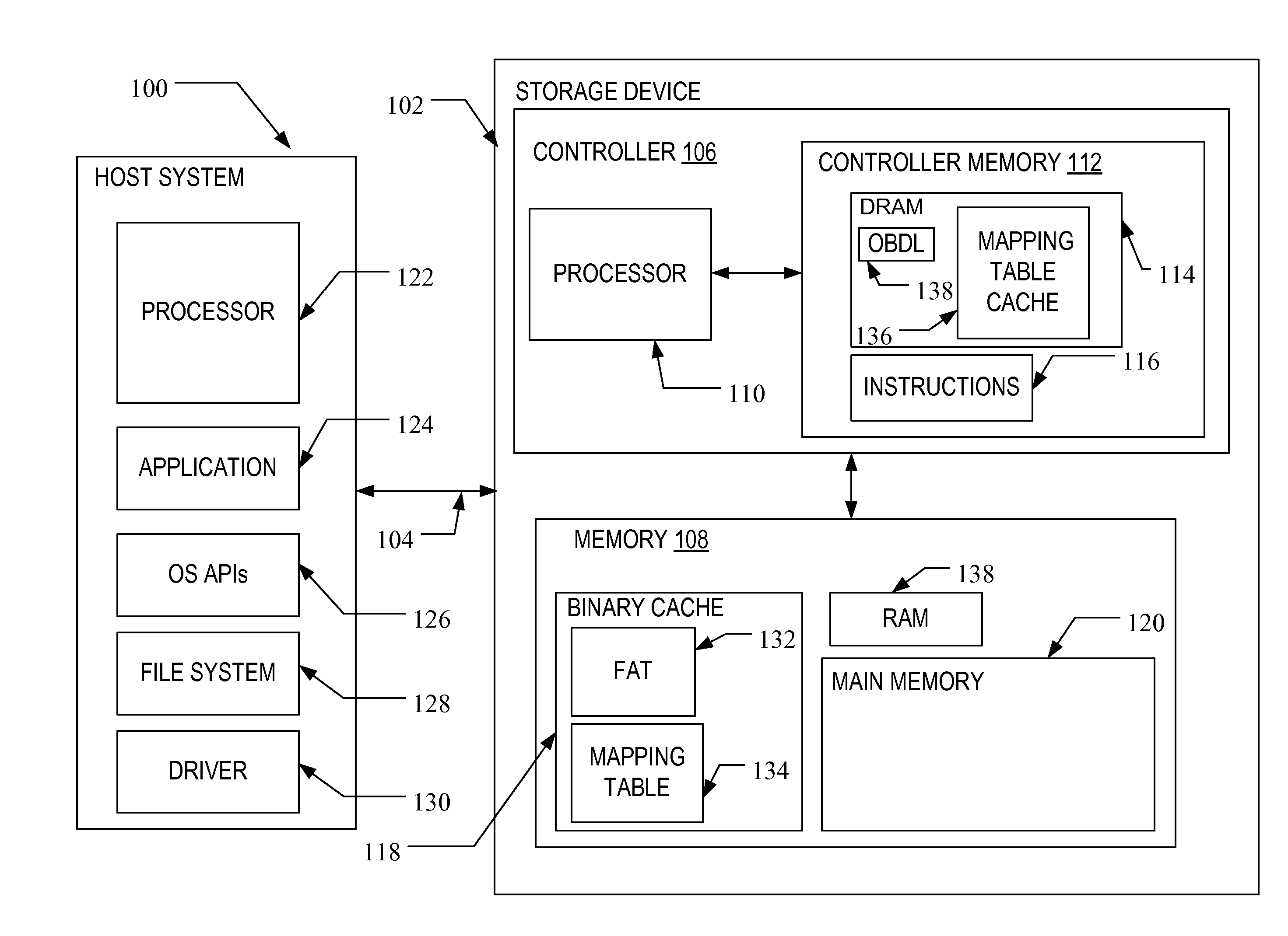
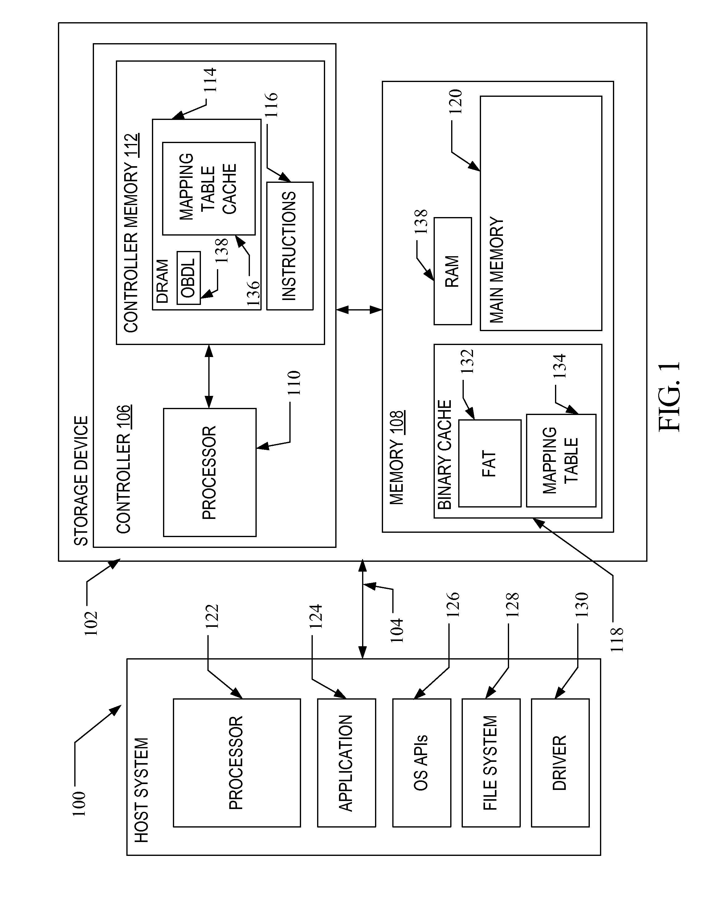
[0021]A flash memory system suitable for use in implementing aspects of the invention is shown in FIG. 1. A host system 100 stores data into, and retrieves data from, a storage device 102. The storage device 102 may be embedded in the host system 100 or may exist in the form of a card or other removable drive, such as a solid state disk (SSD) that is removably connected to the host system 100 through a mechanical and electrical connector. The host system 100 may be any of a number of fixed or portable data generating devices, such as a personal computer, a mobile telephone, a personal digital assistant (PDA), or the like. The host system 100 communicates with the storage device over a communication channel 104.

[0022]The storage device 102 contains a controller 106 and a memory 108. As shown in FIG. 1, the controller 106 includes a processor 110 and a controller memory 112. The processor 110 may comprise a microprocessor, a microcontroller, an application specific integrated circuit ...


PUM


Abstract

A method and system are disclosed for handling logical-to-physical mapping in a storage device. The method includes the storage device storing in fast access memory, such as DRAM, only a fixed-size subset of the primary mapping table in non-volatile memory, along with contiguity information of physical addresses for logical address not in the subset that are adjacent to the logical addresses in the subset. The system includes a storage device having volatile memory, non-volatile memory and a controller in communication with the volatile and non-volatile memory that is configured to carry out the method noted above.

Description

TECHNICAL FIELD[0001]This application relates generally to a method and system for managing the mapping of data in a data storage device.BACKGROUND[0002]Non-volatile memory systems, such as flash memory, are used in digital computing systems as a means to store data and have been widely adopted for use in consumer products. Flash memory may be found in different forms, for example in the form of a portable memory card that can be carried between host devices or as a solid state disk (SSD) embedded in a host device. In SSDs or similar storage devices, a fine granularity logical-to-physical address mapping table is often helpful to provide improved performance. This table can typically be very large. The full table, or subparts of it, is generally necessary to perform read and write tasks, so it is desirable to store a working copy of the mapping table in fast access memory such as dynamic random access memory (DRAM) to ease read and write overhead. However, it may not be economically...

Claims


Application Information

Patent Timeline
Patent Type & Authority Applications(United States)
IPC IPC(8): G06F3/06
CPCG06F3/0611G06F3/0685G06F3/064G06F12/0246G06F12/0607G06F12/0866G06F2212/1016G06F2212/7205G06F2212/7208G06F2212/1044G06F2212/7201G11C7/1072
Inventor THOMAS, NICHOLAS JAMES
Owner SANDISK TECH LLC
Why Eureka
Try Eureka