Quadrature lc tank digitally controlled ring oscillator

a digital control and ring oscillator technology, applied in the direction of oscillator generators, pulse generation by logic circuits, pulse techniques, etc., can solve the problems of good phase noise performance of this oscillator, and achieve the effect of avoiding quality factor degradation of lc tanks, good phase noise performance and high efficiency

Inactive Publication Date: 2015-12-24
TECH UNIV DELFT
View PDF11 Cites 19 Cited by
  • Summary
  • Abstract
  • Description
  • Claims
  • Application Information

AI Technical Summary

Benefits of technology

[0015]The present invention is a quadrature LC tank based digitally controlled ring oscillator (DCO). The oscillator structure incorporates a plurality of stages, each stage including an inverter and a series LC tank. Four stages are coupled together to create a 360 degree phase shift around a loop. The oscillation frequency of the oscillator is the same as the resonant frequency of each LC tank, therefore it avoids quality factor degradation of LC tanks found in the prior art. In one example embodiment, class-D amplifiers are used to drive each of the LC tanks Capacitor banks at the input and output of the buffers provide coarse and fine tuning of the frequency of oscillation. The high efficiency exhibited by these amplifiers results in very good phase noise performance of this oscillator. The oscillator utilizes a startup circuit to launch oscillation upon power on.

Problems solved by technology

The high efficiency exhibited by these amplifiers results in very good phase noise performance of this oscillator.

Method used


Image

  • Quadrature lc tank digitally controlled ring oscillator
  • Quadrature lc tank digitally controlled ring oscillator
  • Quadrature lc tank digitally controlled ring oscillator

Examples


second embodiment

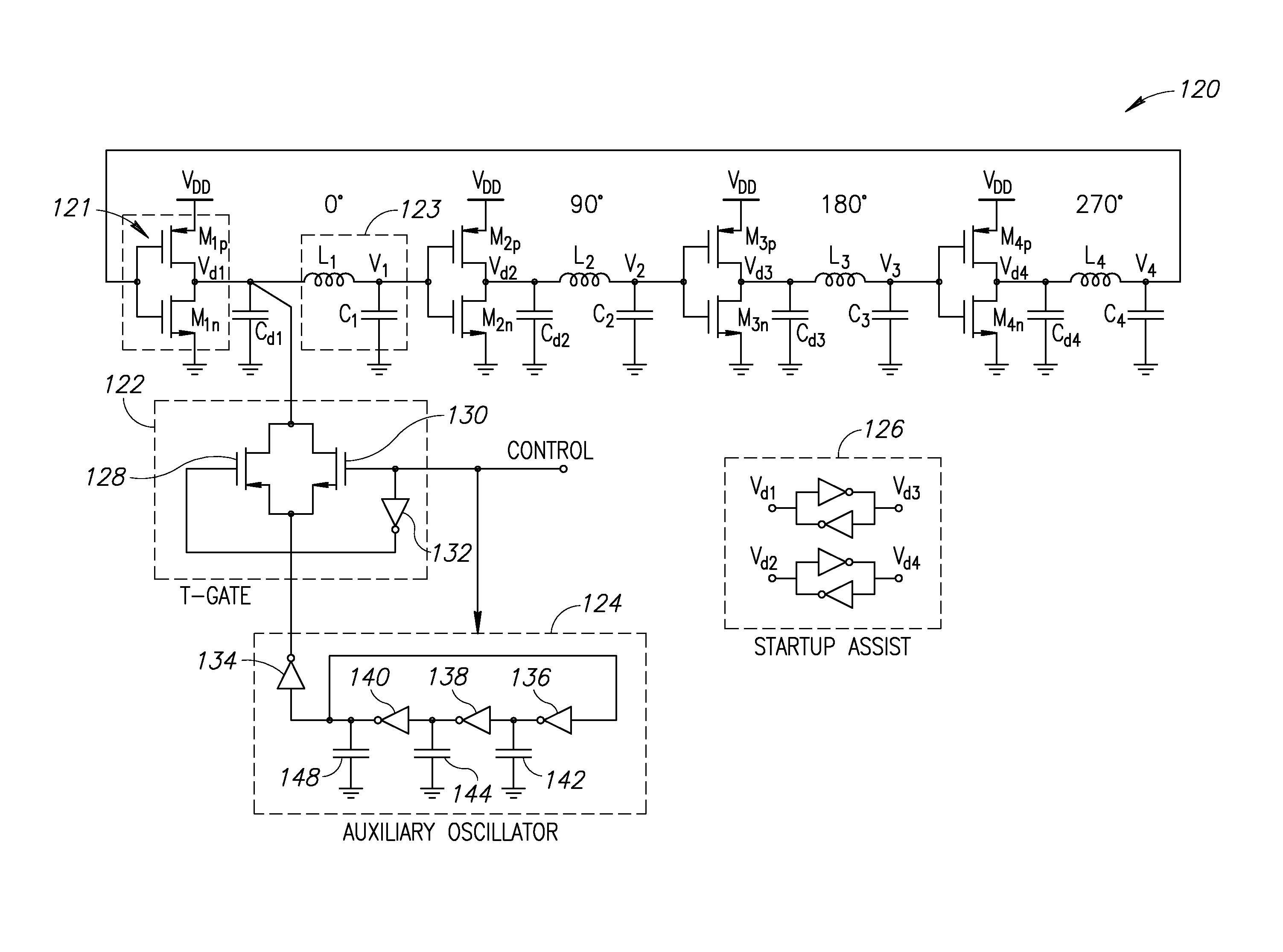
[0065]A circuit diagram illustrating the ring oscillator of the present invention is shown in FIG. 10. The oscillator, generally referenced 170, comprises a plurality of stages, e.g., four, with each stage comprising a buffer 191 coupled to an LC tank 193. In this example, the buffer comprises an inverter and the LC tank comprises L1-4 172 and C1-4. Note that capacitors Cg1-4 and the parasitics of subsequent inverters can be also considered as part of C1-4. The oscillator also comprises starter circuitry 178 and an I / O interface 176 for configuring the capacitor selection which controls the coarse and fine tuning of the frequency of oscillation. The startup circuitry comprises an auxiliary oscillator 180, T-gate 182 and dummy T-gates 184.

[0066]In one embodiment, the oscillator 170 utilizes four relatively small inductors to save area. Consequently, the inductors have a very low quality factor of about 1.5 to 2. In another embodiment, the oscillator uses four regular size inductors w...

third embodiment

[0072]A circuit diagram illustrating the ring oscillator of the present invention is shown in FIG. 11. The oscillator, generally referenced 181, comprises a plurality of stages, e.g., four, with each stage comprising a buffer 195 coupled to an LC tank 197. In this example, the buffer comprises an inverter and the LC tank comprises L1-4 183 and C1-4. The oscillator also comprises starter circuitry 187 and an I / O interface 185 for configuring the capacitor selection which controls the coarse and fine tuning of the frequency of oscillation. The startup circuitry comprises an auxiliary oscillator 171, T-gate 189 and dummy T-gates 173. The oscillator also comprises back to back inverter gates 199 similar to the back to back inverters 126 of FIG. 9A. The inverters 199 are coupled to the nodes Vd1-d4 and are operative to assist in startup, for example in the low area (LA) version of the oscillator. The operation of the oscillator 181 is similar to that of oscillator 170 of FIG. 10 and will...

fourth embodiment

[0075]A circuit diagram illustrating the ring oscillator of the present invention having mutual coupling between inductors is shown in FIG. 13. In this circuit, generally referenced 200, L1 and L3 as well as L2 and L4 are magnetically coupled to act as transformers. Relatively low Q inductors are used where each coupled L is 180 degrees out of phase. Otherwise, the operation of the circuit is similar to that of the oscillator of FIGS. 10 and 11.


PUM


Abstract

A quadrature LC tank based digitally controlled ring oscillator (DCO). The oscillator structure incorporates a plurality of stages, each stage including a buffer and a series LC tank. Four stages are coupled together to create a 360 degree phase shift around a loop. The oscillation frequency of the oscillator is the same as the resonant frequency of each LC tank, therefore it avoids quality factor degradation of LC tanks found in the prior art. In one example embodiment, class-D amplifiers are used to drive each of the LC tanks Capacitor banks before at the input and output of the buffers provide coarse and fine tuning of the frequency of oscillation. The high efficiency exhibited by these amplifiers results in very good phase noise performance of this oscillator. The oscillator utilizes a startup circuit to launch oscillation upon power on.

Description

REFERENCE TO PRIORITY APPLICATION[0001]This application claims priority to U.S. Provisional Application Ser. No. 62 / 016,399, filed Jun. 24, 2014, entitled “Series LC Ring Oscillator,” incorporated herein by reference in its entirety.FIELD OF THE INVENTION[0002]The present invention relates generally to digitally controlled oscillators (DCO) and in particular to a quadrature LC tank based digitally controlled ring oscillator.BACKGROUND OF THE INVENTION[0003]Clock generator circuits are well known circuits that are used in a myriad of applications. In modern integrated wireless / wireline receivers, transmitters and transceivers, as well as digital processors and system-on-chip (SoC) circuits, clock generator circuits are an essential block. In particular, quadrature clock generator circuits are often used to generate multiple clock signals 90 degrees apart from each other. To reach a very high data rate in clock and data recovery integrated circuits, a multiphase oscillator is typicall...

Claims


Application Information

Patent Timeline
Patent Type & Authority Applications(United States)
IPC IPC(8): H03K5/13H03K3/011
CPCH03K5/133H03K3/011H03K3/0322H03B5/1228H03B5/1212H03L3/00H03B2200/0074H03B5/124H03B2201/0208H03K3/0315H03B27/00H03B5/1852
Inventor TOHIDIAN, MASSOUDSTASZEWSKI, ROBERT BOGDANAHMADY, ALI FOTOWATMEHR, SEYED AMIR REZA AHMADIKAMAREI, MAHMOUDNDAGIJIMANA, FABIEN
Owner TECH UNIV DELFT
Why Eureka
Try Eureka