Co2 capture from co2-rich natural gas

a technology of co2 and natural gas, applied in the field of co2 capture from co2rich natural gas, can solve the problem of reducing the compression duty of the system, and achieve the effect of reducing the capital cost of the compressor, great overall savings of capital and energy, and working very efficiently

Inactive Publication Date: 2015-12-31
XU JIANGUO
View PDF4 Cites 24 Cited by
  • Summary
  • Abstract
  • Description
  • Claims
  • Application Information

AI Technical Summary

Benefits of technology

[0008]It is surprisingly discovered in the present invention that CO2 can be cost effectively separated from a gas mixture containing CO2, methane and heavier hydrocarbons, using a distillation column (prefractionator) to first remove the heavier hydrocarbons to such a low level that a physical absorption process involving one or more lower boiling absorbents can also be used very efficiently. In addition, it is found that it is even possible to use a stripping section alone, i.e., at least one of the feed location is at the top of the distillation column, to remove the heavy hydrocarbons to levels acceptable for efficient operation of these physical absorption processes.
[0009]It is further discovered that such processes do not have to use external refrigerant for cooling. Instead, if the liquid CO2-rich stream from the bottom of the prefractionator vaporizes at different pressures, and if one or more of the CO2 vaporization pressures is below that of the prefractionator, the heat transfer ΔT's in the heat exchangers can be made more even, while the power needed to compress CO2 to the desired pressure is greatly reduced,

Problems solved by technology

Setting the pressure of the prefractionator at a different level from the pressures of the subst

Method used


Image

  • Co2 capture from co2-rich natural gas
  • Co2 capture from co2-rich natural gas
  • Co2 capture from co2-rich natural gas

Examples


example-1

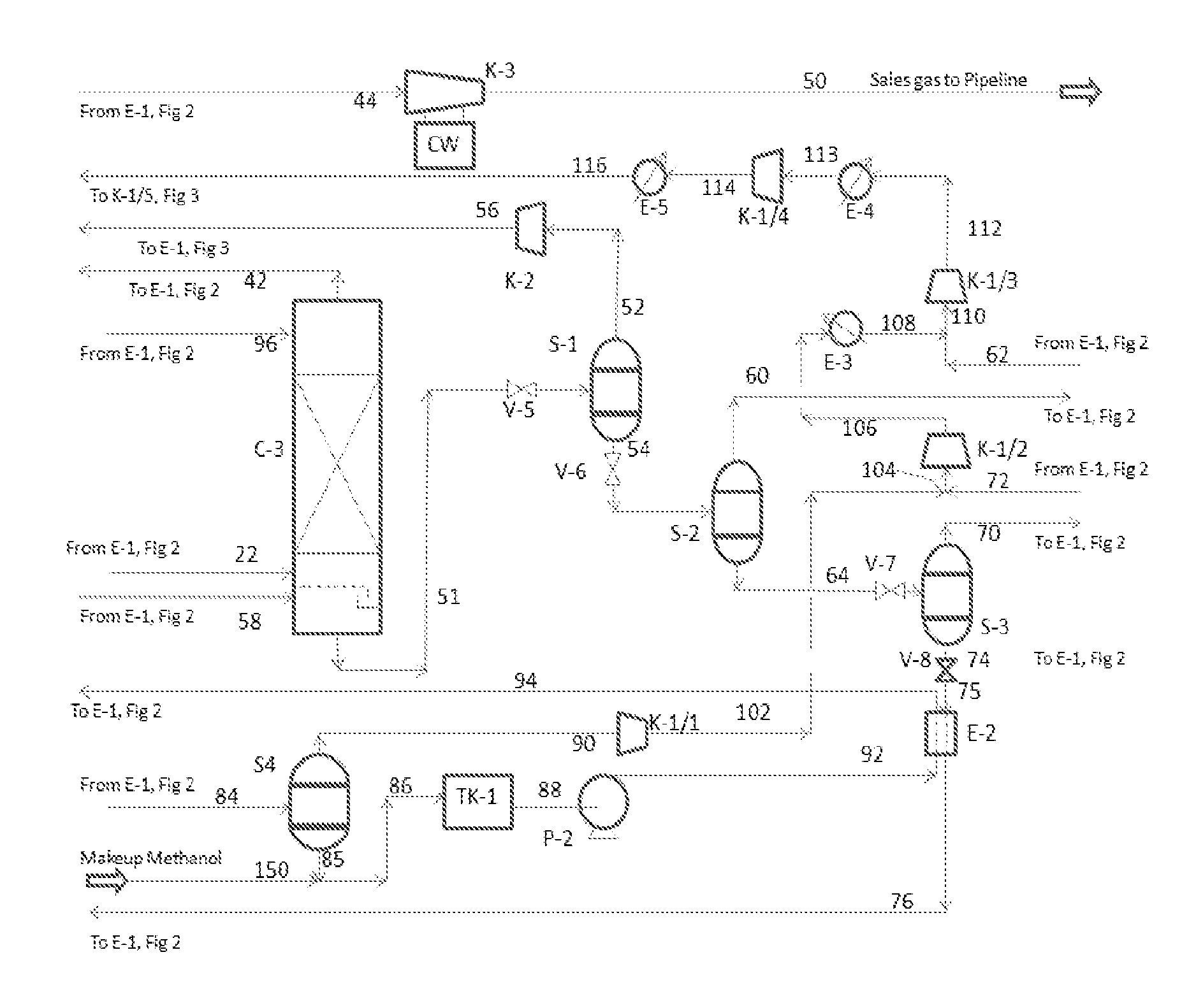
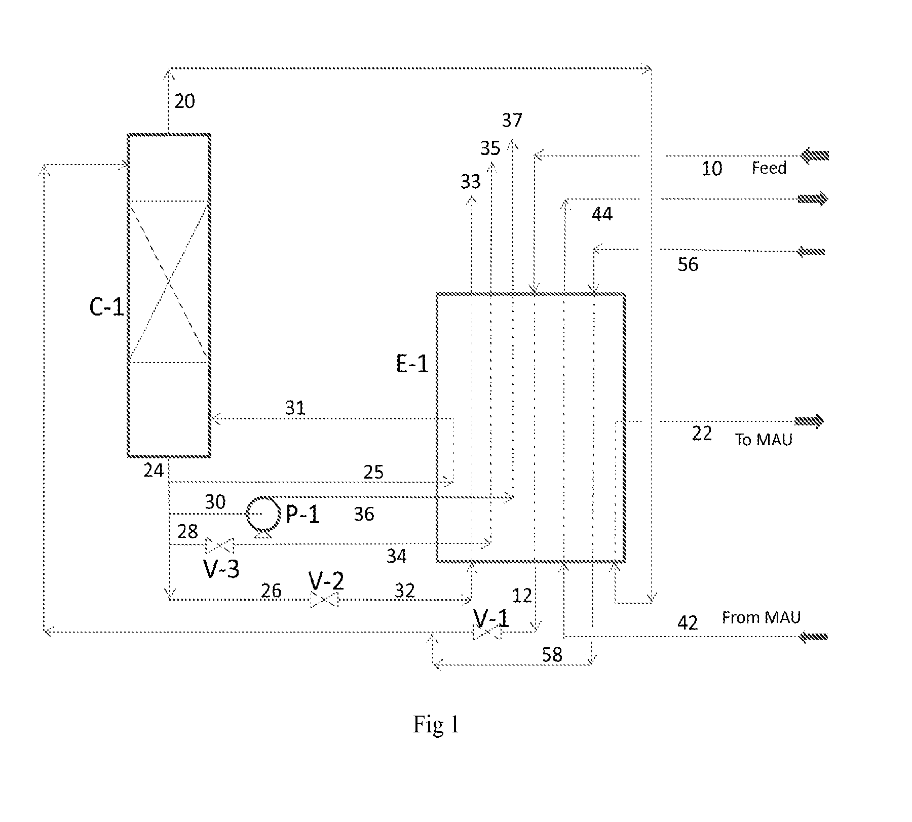
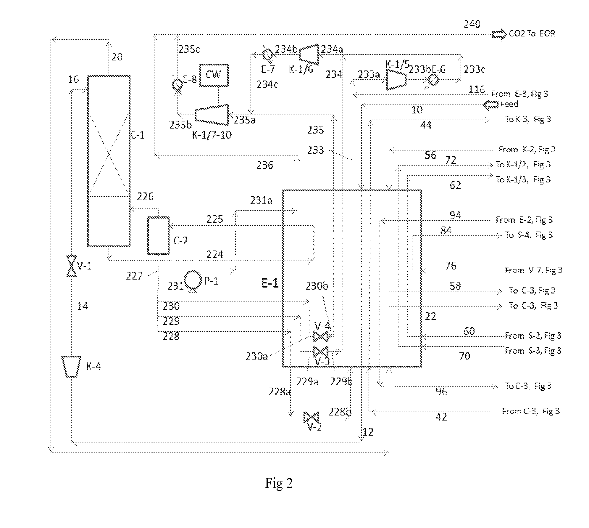
[0073]The Process Flow Diagram (PFD) is shown in FIG. 1. In the process, the feed gas mixture of CO2, methane, and small amounts of nitrogen and heavier hydrocarbons such as ethane, propane, butanes, pentanes, and hexanes at 800 psia and 100° F., in line 10, is first cooled and condensed in the combined reboiler and “second heat exchanger” (to be called Main Heat Exchanger), E-1. The condensed feed stream, in line 12, is let down in pressure to close to 483 psia by the Feed JT-valve, V-1, and fed to the top of the Prefractionator, C-1. The methane enriched overhead vapor, in line 20, from the top of Prefractionator C-1 is heated in the Main Heat Exchanger, E-1, and then taken out of E-1 at an intermediate location and sent for further CO2 removal in methanol absorption unit (to be called MAU, not shown).

[0074]The essentially CO2 and heavier hydrocarbons (0.1 mol % methane) bottoms liquid, to be called first stream, in line 24, of the Prefractionator, C-1, is split into four substrea...

example-2

[0081]This process is developed for CO2 capture from a natural gas containing 65 mol % CO2, similar to that in the example used by Ross and Cueller. The feed gas is at 1125 psia. The CO2 product is delivered at 1900 psia, and the (essentially methane) sales gas is delivered 1175 psia. Both are the same as those in Ross and Cueller's paper. Ross and Cueller claimed that using the Ortloff DRCF-SELEXOL hybrid process, they were able to reduce the power consumption from 81.9 MW needed for the conventional SELEXOL-only process to 45.5 MW and capital cost by $50 MM for a 400 MMSCFD feed gas flow plant.

[0082]Ross and Cueller did not specify the exact composition of the natural gas, but mentioned “65% CO2 and 35% hydrocarbon, predominately methane”. We assumed the feed contains 65 mol % CO2, 32 mol % methane, 1.46 mol % ethane, 0.41 mol % propane, 0.09 mol % isobutene, 0.16 mol % n-butane, 0.09 mol % isopentane, 0.05% n-pentane, 0.24 mol % n-hexane, and 0.5% nitrogen to mimic a “normal” gas...


PUM

PropertyMeasurementUnit
Temperatureaaaaaaaaaa
Pressureaaaaaaaaaa

Abstract

It is described a prefractionation-physical absorption hybrid process and system for separation of a CO2-natural gas mixture containing more than 26 mol % CO2 and 0.1 mol % to 15 mol % in total one or more heavier hydrocarbons, such as ethane, propane, butanes, pentanes, and hexanes, with at least 0.0001 mol % in total one or more of pentanes and hexanes, particularly, a self-refrigerated process and system involving methanol as the absorbent.

Description

CROSS-REFERENCE TO RELATED APPLICATIONS[0001]This application claims priority to U.S. Provisional Patent Application No. 61 / 767,791, filed on Feb. 21, 2013, and U.S. Provisional Patent Application No. 61 / 818,885, filed on May 2, 2013, each of which is hereby incorporated by reference herein in its entirety.BACKGROUND OF THE INVENTION[0002]Some gases from oil wells or other sources contain both methane and high concentration levels, such as greater than 26 mol %, of carbon dioxide (CO2). These gases normally contain smaller amounts of higher hydrocarbons, and sometimes also a small amount of nitrogen. It is desirable to separate CO2 from methane to produce a methane gas with a CO2 concentration typically of less than 2-4% so that it can be sold as a pipeline fuel gas while the captured CO2 can be used for enhanced oil recovery or other purposes. This can be done by conventional CO2 separation processes such as absorption with a high boiling solvent, such as dimethyl ethers of polyeth...

Claims


Application Information

Patent Timeline
IPC IPC(8): C10L3/10C07C7/00F25J3/02C07C7/08C01B31/20B01D53/14C10G7/08C07C7/11C01B32/50
CPCB01D53/002B01D53/1431B01D53/1475B01D2257/504C10L3/104C10G7/08C07C7/11C07C7/08B01D2252/2021B01D53/1493C07C7/005Y02P20/152Y02C10/06Y02C10/08C01B32/50Y02C20/40Y02P20/151
Inventor XU, JIANGUO
Owner XU JIANGUO
Why Eureka
Try Eureka