
Ion implantation compositions, systems, and methods

a composition and ion beam technology, applied in the field of ion beam implantation compositions, systems and methods, can solve the problems of premature failure of ion beams, energy high voltage sparking, and instability of ion beams

Active Publication Date: 2015-12-31
ENTEGRIS INC
View PDF5 Cites 9 Cited by
  • Summary
  • Abstract
  • Description
  • Claims
  • Application Information

AI Technical Summary

Benefits of technology

The present patent relates to methods and compositions for ion implantation. Specifically, it relates to methods for implanting selenium from a feedstock gas containing selenium as a dopant species, using a co-flow gas to prevent failure modes such as sputtering and solids buildup. The selenium-containing feedstock gas can be ionized and the selenium ions can be implanted in a substrate. The patent also describes a system for carrying out the method, including a selenium dopant species and a co-flow gas. The technical effects of the patent include improved efficiency and reliability in ion implantation processes, as well as enhanced operation of the ion implantation system.

Problems solved by technology

In reality, feedstock gas ionization and fragmentation can results in such undesirable effects as arc chamber components etching or sputtering, deposition on arc chamber surfaces, redistribution of arc chamber wall material, etc.
These effects contribute to ion beam instability, and may eventually cause premature failure of the ion source.
Residues of feedstock gases and their ionization products, when deposited on the high voltage components of the ion implanter tool, such as the source insulator or the surfaces of the extraction electrodes, can also cause energetic high voltage sparking.
Such sparks are another contributor to beam instability, and the energy released by these sparks can damage sensitive electronic components, leading to increased equipment failures and poor mean time between failures (MTBF).
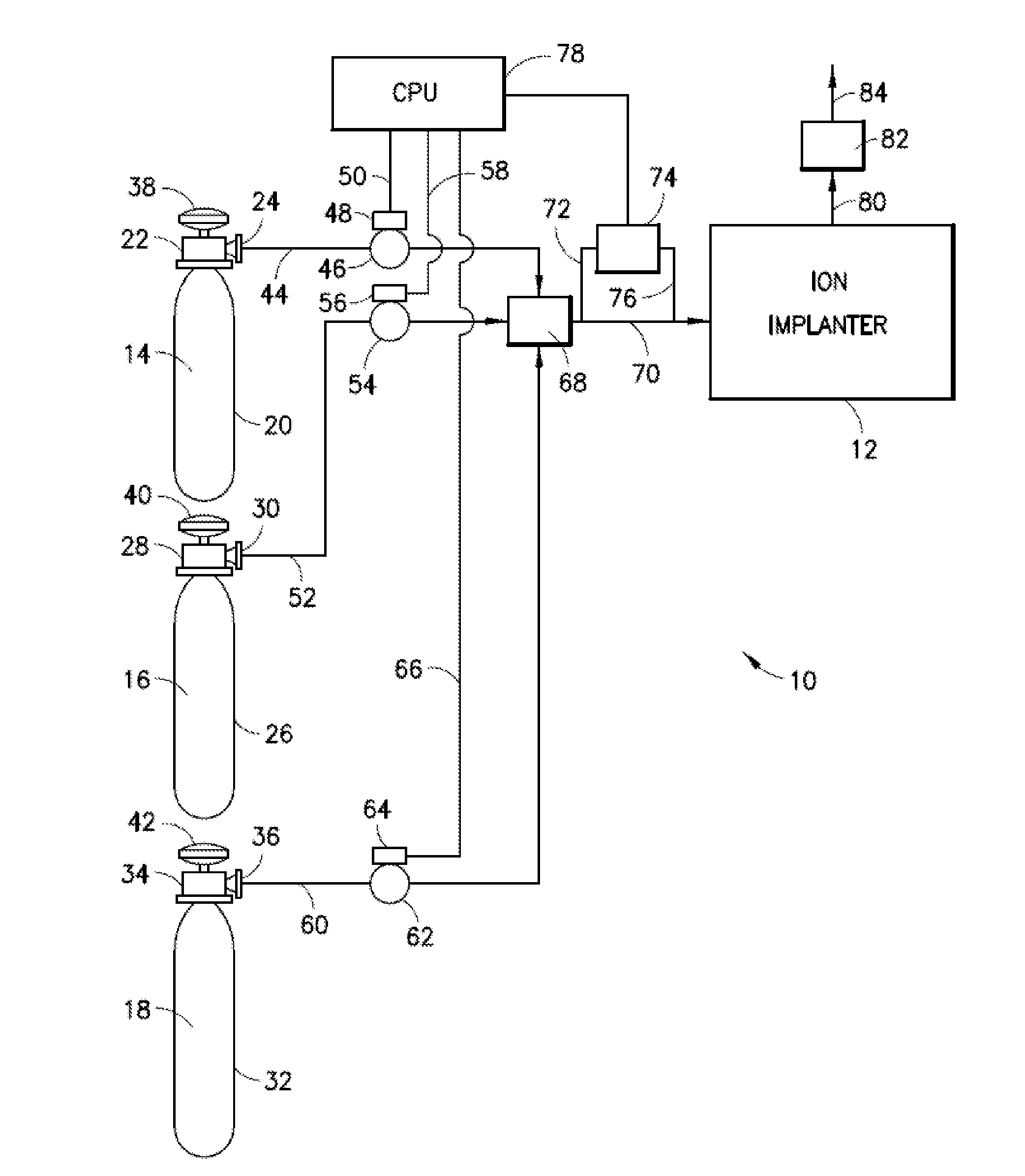
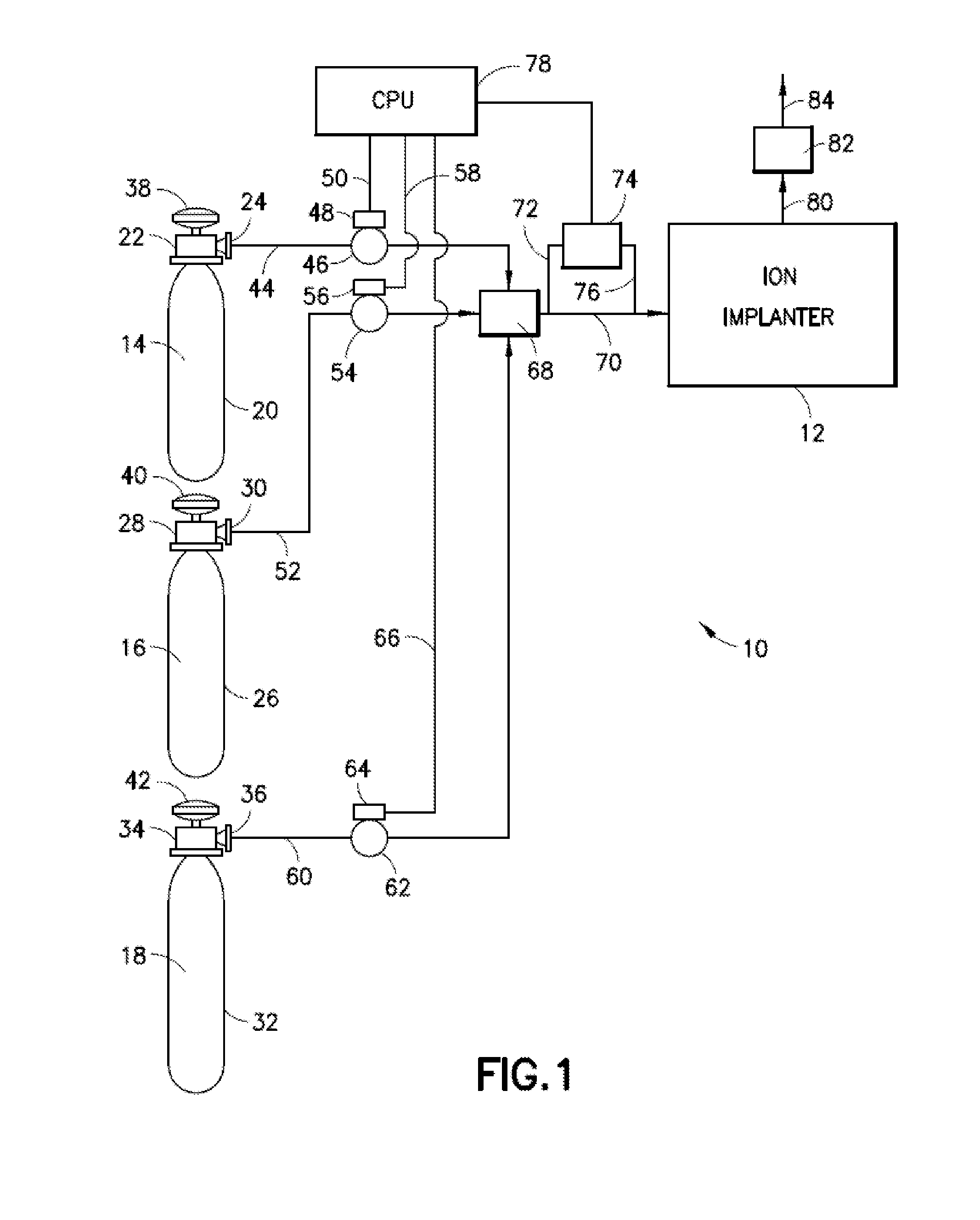
In ion implanters that run a high percentage of hydride gases as feedstock gases or co-flow gases (co-flow gases are gases that are contemporaneously flowed to the implanter with feedstock gases, either in mixture with the feedstock gas, or as piped to the ionization chamber of the implanter in a separate flow conduit from the conduit flowing the feedstock gas), ion source failure modes typically include (i) excessive sputtering of the cathode, resulting in so-called “punch-through” of the cathode, (ii) excessive deposition of solids and insulating surfaces, resulting in electrical shorts or “glitching,” (iii) solids buildup that causes shorting between two components of differing electric potential, and (iv) solids buildup on the cathode that causes loss of electron emission efficiency resulting in loss of ion beam current.
As microelectronic and semiconductor devices become progressively smaller, ion implantation is frequently required to be conducted at correspondingly lower energies to provide shallow implanted regions, and such low-energy operation carries the disadvantages of higher cost and reduced tool productivity.

Method used


Image

  • Ion implantation compositions, systems, and methods
  • Ion implantation compositions, systems, and methods

Examples


Embodiment Construction

[0041]The present disclosure relates to ion implantation systems, methods and compositions.

[0042]As used herein, and in the appended claims, the singular forms “a”, “and”, and “the” include plural referents unless the context clearly dictates otherwise.

[0043]Organo moieties of compounds herein, and organic compounds themselves, may be of any suitable type, and may for example comprise elements C, H, and optionally heteroatoms such as O, N, Si, etc. Such moieties and organic compounds of the present disclosure may have any suitable carbon number, e.g., C1-C12, or higher, in stoichiometric ratio with other elements therein.

[0044]As used herein, the identification of a carbon number range, e.g., C1-C12, is intended to include each of the component carbon number moieties within such range, so that each intervening carbon number and any other stated or intervening carbon number value in that stated range, is encompassed, it being further understood that sub-ranges of carbon number within...


PUM

PropertyMeasurementUnit
Natural abundanceaaaaaaaaaa

Abstract

Ion implantation compositions, systems and methods are described, for implantation of dopant species. Specific selenium dopant source compositions are described, as well as the use of co-flow gases to achieve advantages in implant system characteristics such as recipe transition, beam stability, source life, beam uniformity, beam current, and cost of ownership.

Description

CROSS-REFERENCE TO RELATED APPLICATION[0001]The benefit of priority of U.S. Provisional Patent Application No. 61 / 773,135 filed Mar. 5, 2013 in the name of Oleg Byl, et al. for “ION IMPLANTATION COMPOSITIONS, SYSTEMS, AND METHODS” is hereby claimed under the provisions of 35 USC 119. The disclosure of U.S. Provisional Patent Application No. 61 / 773,135 is hereby incorporated herein by reference, in its entirety, for all purposes.FIELD[0002]The present disclosure relates to ion implantation systems and methods, and to compositions for ion implantation.DESCRIPTION OF THE RELATED ART[0003]Ion implantation is a widely used process in the manufacture of microelectronic and semiconductor products, being employed to accurately introduce controlled amounts of dopant impurities into substrates such as semiconductor wafers.[0004]In ion implantation systems employed in such applications, an ion source typically is employed to ionize a desired dopant element gas, and the ions are extracted from ...

Claims


Application Information

Patent Timeline
IPC IPC(8): H01J37/317H01L21/22H01J37/08
CPCH01J37/08H01J37/3171C23C14/48H01J2237/08H01L21/2225H01J2237/006
Inventor BYL, OLEGSWEENEY, JOSEPH D.TANG, YINGRAY, RICHARD S.
Owner ENTEGRIS INC
Learn More