Methods for fuel conversion

a fuel conversion and fuel technology, applied in the direction of energy input, molten salt/metal gasification, organic chemistry, etc., can solve the problems of large carbon dioxide emission into the environment, significant capital and operational costs,

Active Publication Date: 2016-01-07
OHIO STATE INNOVATION FOUND
View PDF10 Cites 22 Cited by
  • Summary
  • Abstract
  • Description
  • Claims
  • Application Information

AI Technical Summary

Problems solved by technology

Current conversion methods of carbonaceous fuels may emit large quantities of carbon dioxide to the environment and may require significant capital and operational costs.

Method used


Image

  • Methods for fuel conversion
  • Methods for fuel conversion
  • Methods for fuel conversion

Examples


example 1

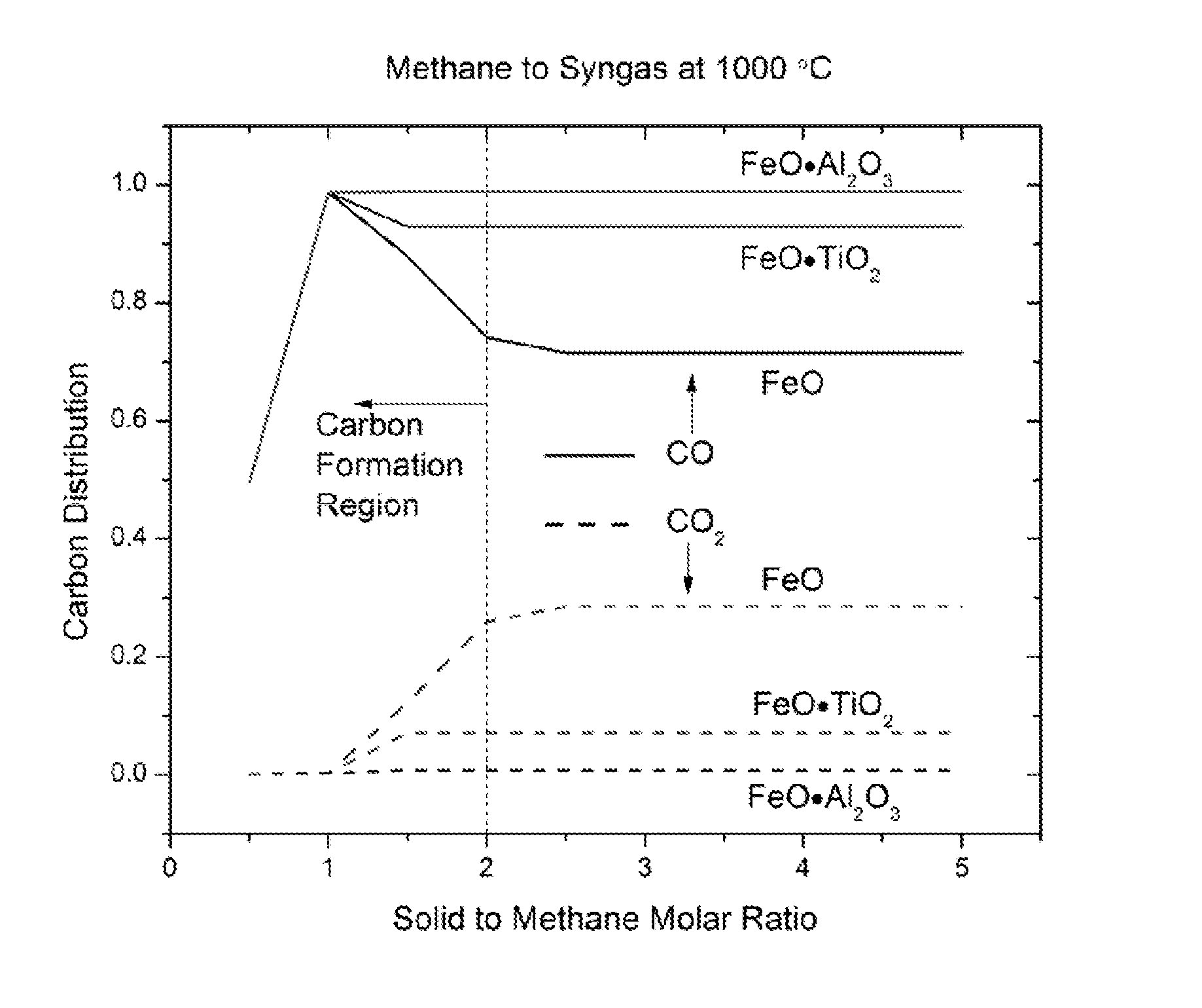
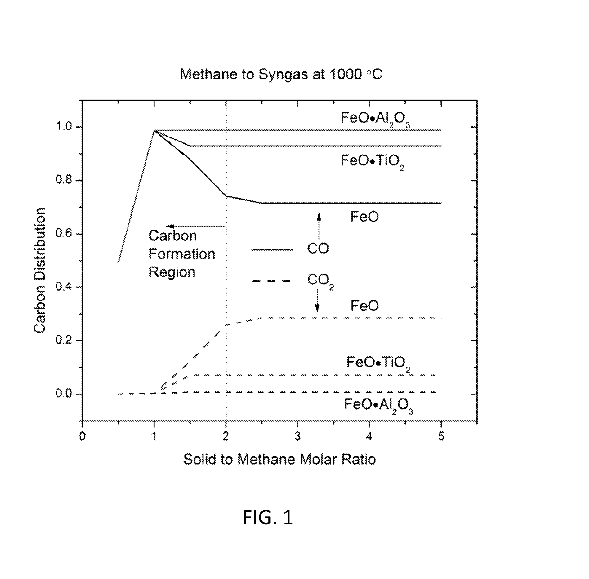
[0067]A fixed bed experiment was conducted to study the methane to syngas reaction. The lower section of the reactor was filled with 23.1 g FeO—TiO2 particles, and the upper section was filled with 8.3 g Fe2O3—TiO2 particles. When the temperature of the reactor reached 990° C., 50 mL / min CH4 and 50 mL / min N2 was injected into the reactor by digital mass controllers. The outlet gas composition was analyzed using a CAI gas analyzer as well as a gas chromatography. The gas concentration at the outlet reached a quasi-steady state in half an hour with methane conversion >95%, CO:CO2 ratio around 10, CO:H2 ratio around 1:2.

example 2

[0068]A moving bed reactor test apparatus was constructed, as shown in FIG. 12, and experiments were conducted to study the solid feedstock to syngas reaction using Powder River Basin (PRB) coal as prototype coal. The PRB coal tested has about 25% moisture and the corresponding molecular formula may be CH0.8O0.2 on a dry basis. The coal powder was mixed with particles at the mass ratio of 1:5 and then fed into the moving bed system from the top in a batch mode. The solid flowrate was controlled to be 20 g / min by the screw feeder at the bottom. The temperature was controlled by the external heating to be 1030° C. At the steady state, the coal conversion is over 90%, H2 / CO ratio fluctuated between 0.5-0.7 and CO / CO2 ratio fluctuated between 5-12, as shown in FIG. 13, respectively. The fluctuation is due to the batch feeding mode of the solid material. Furthermore, CH4 was also co-injected to adjust the H2 / CO ratio. The co-injection of CH4 (870 ml / min, coal 2.7 g / min, particles 20 g / mi...

example 3

[0069]A moving bed reactor test was conducted to study the solid feedstock conversion to syngas using biomass. The corresponding molecular formula was CH1.4O0.6. The biomass material was mixed with particles at a mass ratio of 1:3 and then injected into the moving bed system from the top. The solid fuel and composite particles followed a co-current contacting mode. The composite particle flowrate was controlled to 20 g / min using the screw feeder at the bottom. The temperature was controlled to 1040° C. using the external heaters. At steady state operation, the biomass conversion was over 95% with CO:CO2 ratio around 10 and CO:H2 ratio around 1:0.8. In this case, the carbon monoxide and hydrogen concentration in the high quality syngas from the syngas production reactor was higher than 91 mol %. Additionally, CH4 was co-injected to adjust the CO:H2 ratio. The co-injection of CH4 (540 ml / min, biomass 5 g / min, particles 26 g / min) gave an almost complete fuel conversion (95%) with CO:H2...


PUM

PropertyMeasurementUnit
temperatureaaaaaaaaaa

Abstract

In one embodiment described herein, fuel may be converted into syngas by a method comprising feeding the fuel and composite metal oxides into a reduction reactor in a co-current flow pattern relative to one another, reducing the composite metal oxides with the fuel to form syngas and reduced composite metal oxides, transporting the reduced composite metal oxides to an oxidation reactor, regenerating the composite metal oxides by oxidizing the reduced composite metal oxides with an oxidizing reactant in the oxidation reactor, and recycling the regenerated composite metal oxides to the reduction reactor for sub-sequent reduction reactions to produce syngas. The composite metal oxides may be solid particles comprising a primary metal oxide and a secondary metal oxide.

Description

CROSS REFERENCE TO RELATED APPLICATIONS[0001]This application is related to U.S. Provisional Patent Application No. 61 / 761,016, filed Feb. 5, 2013, entitled “High Quality Syngas Production Using Composite Metal Oxides” (Docket OSU 0080 MA) and to U.S. Provisional Patent Application No. 61 / 779,243, filed Mar. 13, 2013, entitled “Systems and Methods for Co-Current Chemical Looping Systems” (Docket OSU 0080 M2), the teachings of both of which are incorporated by reference herein.BACKGROUND1. Field[0002]The present disclosure relates to chemical looping systems and methods, and specifically to systems and methods for producing syngas from feedstock fuels.2. Technical Background[0003]There is a constant need for clean and efficient energy generation systems. Many of the commercial processes that generate energy carriers such as steam, hydrogen, synthesis gas (syngas), liquid fuels, and / or electricity are based on fossil fuels. Furthermore, the dependence on fossil fuels is expected to co...

Claims


Application Information

Patent Timeline
Patent Type & Authority Applications(United States)
IPC IPC(8): C01B3/34C10J3/57
CPCC01B3/344C10J3/57C10J2300/0916C01B2203/0255C10J2300/0953C10J2300/1807C10J2300/093B01J8/12C01B2203/02C01B2203/1241Y02E60/32Y02P20/133
Inventor FAN, LIANG-SHIHLUO, SIWEIZENG, LIANG
Owner OHIO STATE INNOVATION FOUND
Why Eureka
Try Eureka