Countercurrent heat exchanger/reactor

a heat exchanger and countercurrent technology, applied in indirect heat exchangers, lighting and heating apparatuses, chemical/physical/physicochemical processes, etc., can solve the problems of difficult to maintain separation between opposing streams, the design of headers is one of the most challenging problems, and the heat transfer efficiency is maximized. , the effect of reducing the flow rate of working fluids

Active Publication Date: 2016-01-07
THAR ENERGY
View PDF2 Cites 11 Cited by
  • Summary
  • Abstract
  • Description
  • Claims
  • Application Information

AI Technical Summary

Benefits of technology

[0020]The above embodiments can include one or more of the following advantages. A heat exchanger of the type disclosed herein is useful in many different applications that demand compactness; i.e., high rates of heat transfer in a small package. For example, in utility power generation, recuperators are often employed to recover heat from working fluid from a turbine exhaust and recycle that energy to working fluid that is being heated ahead of the turbine. In these applications, recuperation heat duties can be several times that of the power generated. Without a compact design, these recuperators could become much too large for economical feasibility. This technology is also applicable to heat exchangers that move heat in and out of phase-change materials (PCMs). By minimizing the boundaries of solid-liquid interfaces through the use of microchannels, heat transfer efficiency is maximized and working-fluid flow rates are minimized. This facilitates huge savings at several points around a power cycle—a smaller solar receiver, smaller compressor, smaller recuperator and less waste heat. The manufacturing technology disclosed herein will also extend the commercial applications of microchannel construction to air-to-air and air-to-steam heat exchangers, as might be encountered in waste heat applications.

Problems solved by technology

At channel dimensions that are considered by most as “microchannel” in size, meaning less than 5 millimeters and more likely less than 2 millimeters in diameter, design problems multiply rapidly.
For example, header design (i.e., separation of opposing streams) is one of the most challenging of problems.
Especially in the case of countercurrent flow, it is difficult to maintain separation between opposing streams.
The problem with these approaches, however, is that heat transfer efficiency suffers either from a poor pattern of temperature difference or flow distribution, or both.
However, flow is poorly distributed because of the introduction of the fluid via side ports.
This results in an increase in pressure drop as the number of baffles increases.
However, there is a practical limit to the number of baffles that one can use.
Heat exchangers of this type, however, are limited in both temperature and pressure.
For microchannel heat exchangers the separation of the streams becomes more difficult because of the high density of channels penetrating the tube sheet.
The use of small microchannels improves efficiency in a compact design, but the device may be heavy due to the space taken up by solid, unetched metal underneath the channels.

Method used


Image

  • Countercurrent heat exchanger/reactor
  • Countercurrent heat exchanger/reactor
  • Countercurrent heat exchanger/reactor

Examples


example 1

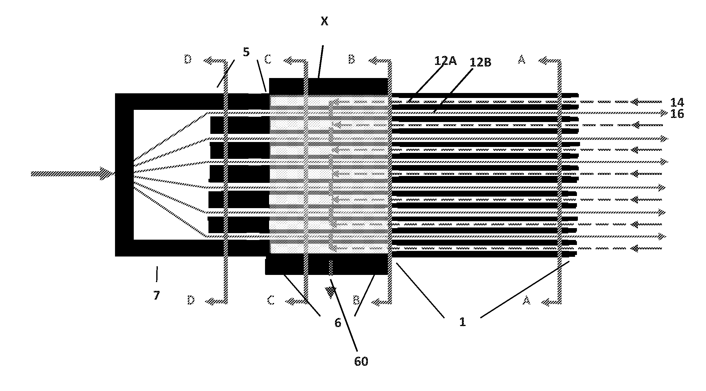
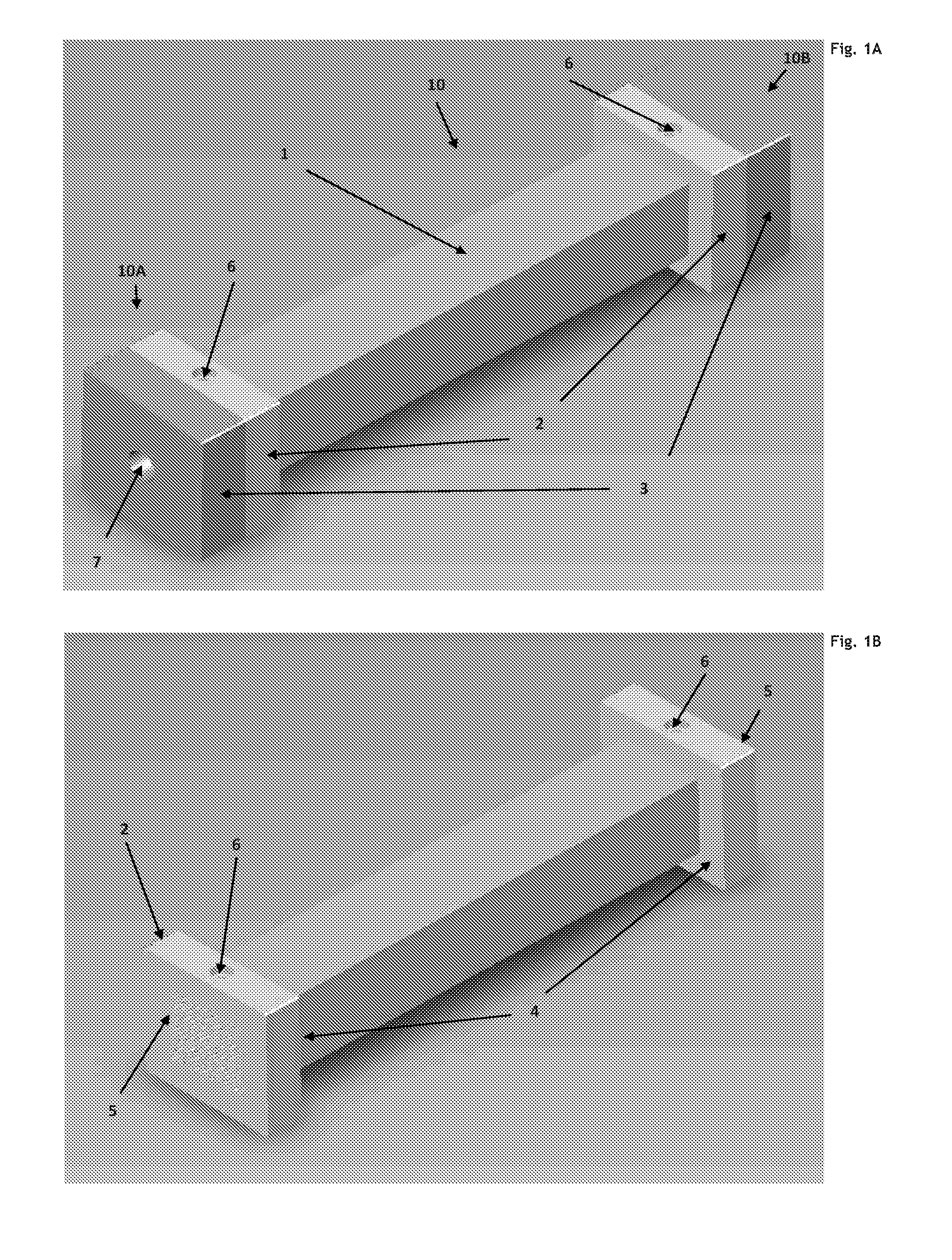
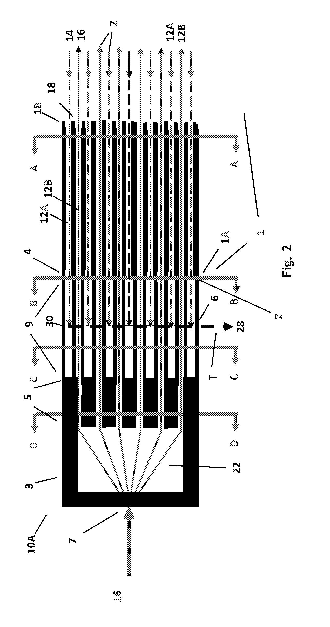
[0059]A heat exchanger as shown in FIG. 1 was fabricated according to the contiguous channel configuration, comprising an array of 25×25 square channels, each 0.6-mm inside height and width, occupying an outside dimension of 1-in by 1-in. The size and shape of the channels (see FIG. 2, 12A) for holding a first stream (14) are substantially the same along the longitudinal axis (z). The size and shape of the channels (12B) are altered as shown in FIGS. 3B-3D. The heat exchanger was additively manufactured. In particular, Inconel 718 was used to form the channels (both 12A and 12B). The total length of the bundle was 6.57 inches. Total internal surface area for one of the two countercurrent streams is 0.1202 m2. Overall areal density (surface area divided by overall volume) is thus 1,116 m2 / m3. In a test with water flowing at rates of 0.38 to 1.08 gallons per minute (see Table 4), the power density ranged from 25.1 to 32.4 MW / m3.

TABLE 4Heat duty: Tests with water25 × 25 channels, 1″× 1...

example 2

[0060]A stainless steel microchannel heat exchanger constructed in accordance with the present disclosure, and having an areal density of 1,351 m2 / m3 in a bundle volume of 65.7 cubic inches, weighing 8.5 lbs., was tested under the conditions described in Table 5. Power density for these cases is in the range of 10 to 11 MW / m3.

TABLE 5Heat duty: Tests with carbon dioxide32 × 20 channels, 1.04″× 2.155″× 29.43″ outer dimensionsHeatPowerFlowrateInletOutletdutydensityCaseStream[GPM][F.][F.][kW]MW / m3A2Hot Side3.45175.697.0−10.810.1Cold Side2.2277.8112.911.1B2Hot Side3.37178.997.3−10.910.0Cold Side2.1979.7115.410.7C2Hot Side6.87167.4101.5−12.111.2Cold Side2.2383.3142.512.1


PUM


Abstract

Counter-flow heat exchanger is constructed with plenums at either end that separate the opposing fluids, the channels of which are arrayed in a checkerboard patterns, such that any given channel is surrounded by channels of opposing streams on four sides—laterally on both sides and vertically above and below.

Description

CROSS-REFERENCE TO RELATED APPLICATION[0001]This application claims benefit of and priority to U.S. Provisional Application Ser. No. 61 / 789,235, filed Mar. 15, 2013, incorporated by reference herein in its entirety.FIELD OF THE INVENTION[0002]This invention relates to the field of single-pass countercurrent heat exchangers, more particularly, this invention relates to such devices that exhibit high areal density.BACKGROUND[0003]It is well known that heat can be transferred between fluids within a given volume more efficiently as the size of the channels that conduct these fluids decreases and the number of channels increases. At channel dimensions that are considered by most as “microchannel” in size, meaning less than 5 millimeters and more likely less than 2 millimeters in diameter, design problems multiply rapidly. For example, header design (i.e., separation of opposing streams) is one of the most challenging of problems. Especially in the case of countercurrent flow, it is diff...

Claims


Application Information

Patent Timeline
Patent Type & Authority Applications(United States)
IPC IPC(8): F28D7/16
CPCF28D7/1607B01J8/087B01J19/006B01J19/0093B01J19/2425B01J19/249F28F9/02F28D7/1653F28D7/1684B01J2219/00788B01J2219/00822B01J2219/00835B01J2219/00849B01J2219/0086B01J2219/00873B01J2219/00891B01J2219/1921B01J2219/1928B01J2219/2462B01J2219/2477B01J2219/2485F28F2260/02
Inventor CHORDIA, LALITDAVIS, JOHN C.
Owner THAR ENERGY
Why Eureka
Try Eureka