Detection system and method of detecting corrosion under an outer protective layer

a detection system and protective layer technology, applied in the field of detection systems, can solve the problems of affecting the environmental, shutting down the entire system, affecting the environmental and safety, and affecting the safety of the environment,

Active Publication Date: 2016-01-07
SUBTERANDT
View PDF2 Cites 25 Cited by
  • Summary
  • Abstract
  • Description
  • Claims
  • Application Information

AI Technical Summary

Benefits of technology

[0026]The various embodiments provide a system that has the ability to observe the sample directly from a distance without having to be rigidly attached to a reference frame; this freedom offers considerable benefit from the practical implementation in a real world scenario. The use of a passive extended source that provides a wide angle illumination represents a significant improvement over the prior art, particularly for viewing non-flat surfaces such as pipes or upright tubes.

Problems solved by technology

Furthermore, these environments can be chemically corrosive or mechanically abrasive.
In terms of negative outcomes, if we consider a pipe in a chemical factory or an oil pipeline running across a desert, rupturing of such a pipe would shut the entire system down and has environmental and safety impact.
More specifically, escaping liquid, such as oil, must be cleaned up and disposed of in a safe fashion, whilst rapid high pressure release of a pressurised liquid travelling in a pipe could result in fragmentation of pipe and, consequently, the generation of high-velocity projectiles from the splintered pipe substrate.
These materials are extremely strong provided their structural integrity remains intact, but any crack or delamination can lead to rapid loss of stiffness and may result in catastrophic failure.
Once deployed in the field, the cost of assessment and the length of time required for performing the assessment increase simply because of the physical inaccessibility of the part under investigation.
In other words, visual or mechanical inspection is difficult simply because of restricted access.
Any covering curtails direct visual assessment, and any covering or coating has hitherto required the use of expensive and accurately located evaluation equipment.
Proactive maintenance therefore has a relatively high cost because an assessment of corrosion under insulation (“CUI”) or corrosion under paint (“CUP”) or corrosion under coatings (“CUC”) requires an active peeling back or outright removal of the insulating material or paint to conduct a visual or other quantitative inspection of the substrate, whereafter a new protective coating or layer must be properly and securely reapplied.
Removal and reapplication of any coating or layer therefore has a cost, with any removal process providing further potential for damaging the substrate.
This illumination approach introduces problems due to specular reflection from the surface, and requires the inspection apparatus (or the sample) to be repositioned at each measurement point.
The requirement for detector orientation and / or sample placement imposes severe constraints on the practical implementation of their techniques in real world environments, particularly those found outdoors on bridges, oil platforms and the like where corrosion presents a significant problem.
The coherent source provides an ability to assess phase in the reflected waves, whereas a non-aligned source is considered problematic from the perspective of feature resolution.
Sample or detector rotation both result in significant apparatus complexity and increased cost, with rotation furthermore reducing the speed of assessment.
The prior art systems of Alfano '728 and QinetiQ '946 can therefore be considered as laboratory-based executions because their construction makes in situ substrate inspection very difficult, if not impossible, but at least highly impractical.
In addition, the use of a powerful artificial coherent source only recovers the reflectivity component of the objects positioned within the scene and so any misalignment or variation of the surface texture of the sample can be misinterpreted as a reflectivity variation even for surfaces free of corrosion, i.e. the systems are subject to a false trigger.

Method used


Image

  • Detection system and method of detecting corrosion under an outer protective layer
  • Detection system and method of detecting corrosion under an outer protective layer
  • Detection system and method of detecting corrosion under an outer protective layer

Examples


Embodiment Construction

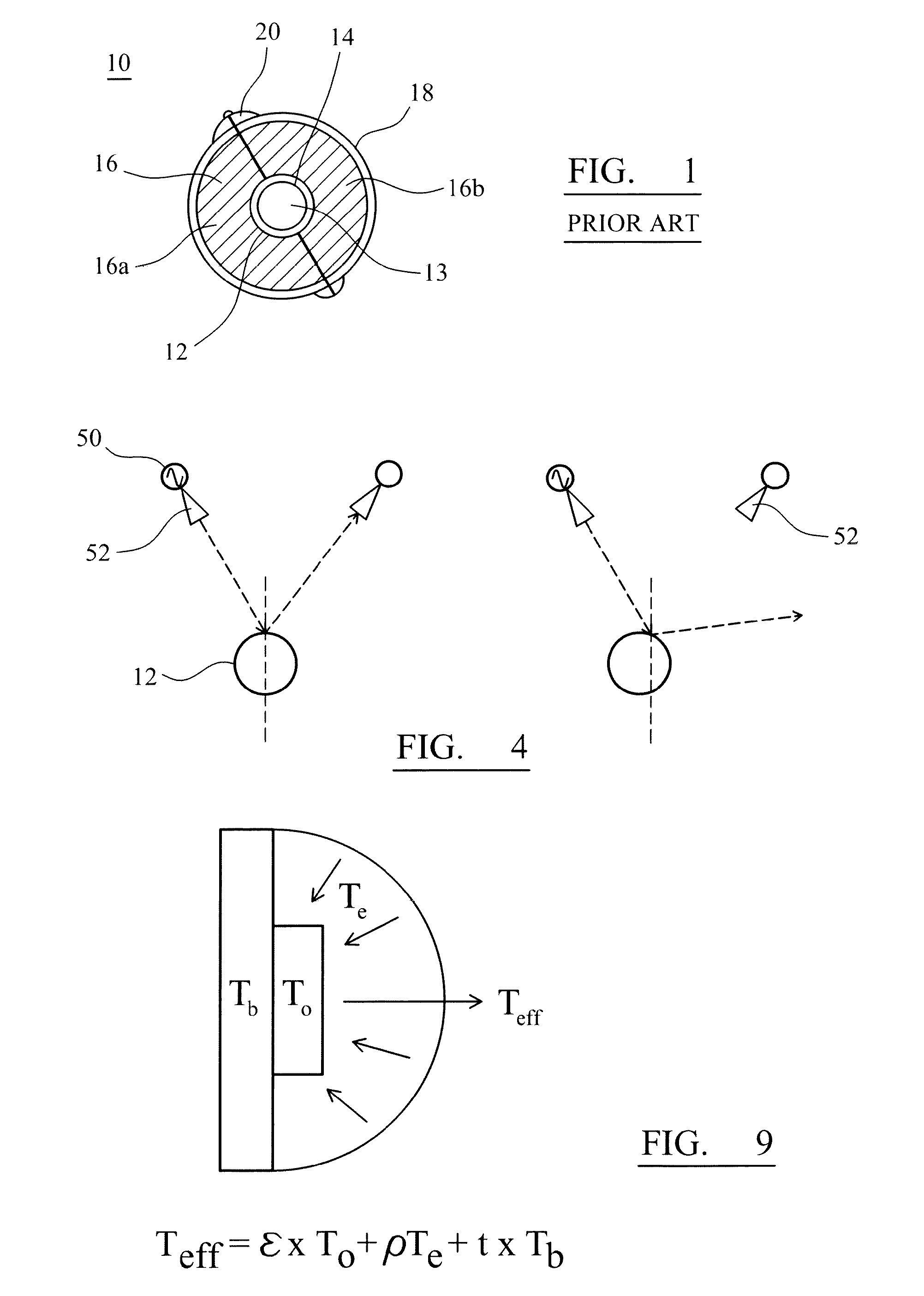
[0038]FIG. 1 shows a typical pipework system 10. A pipe 12 is made of a substrate that is subject to some form of corrosion 14, such as rusting in the case of an iron-based pipe. The pipe 12 may carry, within its interior 13, any number of materials (including oil or other chemicals) and may be internally lined or its substrate externally coated with a protective coating, such as a paint, or otherwise protected by an external insulating layer 16. In the latter respect, the layer 16 may be a thermal lagging which is secured in placed around the pipe of an external jacket 18. The insulating layer 16 may, in fact, be realised by two hemispheres (16a, 16b) which are clamped together by the external jacket 18 in combination with some form of locking mechanism 20 that acts through the external jacket 18. The skilled artisan will understood the arrangement of the pipework system 10 and how the insulating layer 16 is held in place about or otherwise applied (in the sense of being adhered to...


PUM

PropertyMeasurementUnit
temperatureaaaaaaaaaa
electromagnetic frequenciesaaaaaaaaaa
wavelengthsaaaaaaaaaa

Abstract

Incoherent millimetre wave, sub-millimetre wave and terahertz test signals are used to probe metal substrates that are covered by a protective coating or outer layer, such as paint or thermal insulation, obscuring direct assessment of the substrate. The incoherent test signals, which may be from a naturally occurring passive source (such as the sky) and/or from an active noise source, provide signal dispersion and angular variation of the test signals with respect to angular incidence to the substrate. Illumination of the substrate permits differentiation between un-corroded and corroded sections of the sample because reflectivity (and emissivity) from a metal-based substrate is heavily dependent on the surface resistivity which in turn is dependent on the corroded state. A detector/camera is arranged to pick up reflections from the substrate and an associated control system identifies regions of the sample that reflect the test signal illumination differently or otherwise indicate a variation from a reference value. The differences therefore signify the presence or lack of corrosion or, indeed, the presence of other abnormalities within or on the substrate.

Description

FIELD OF THE INVENTION[0001]This invention relates, in general, to detection systems and is particularly, but not exclusively, applicable to detectors (and detection system methodologies) that operate to assess levels of corrosion under outer protective layers or coatings, such as paint, insulation, fireproof cladding or anti-corrosion protective coatings, applied on or over a surface, such as a pipe or wall.SUMMARY OF THE PRIOR ART[0002]The detection and identification of structural anomalies and imperfections (including cracks and fractures, penetrations, porosity variations, corrosion, disbanding and delamination) in substrates is important for quality control, preventative maintenance and especially safety considerations. In this context, the substrate can define the structure of a pipe, panel or frame and may be made from a number of known materials, including metal or composite materials. Once in situ, the mechanical structures formed from such substrates are subjected to a va...

Claims


Application Information

Patent Timeline
Patent Type & Authority Applications(United States)
IPC IPC(8): G01N21/3581G01N17/04G01N21/55G01N22/04
CPCG01N21/3581G01N17/04G01N22/04G01N21/55G01N17/006G01N21/4738G01N21/952G01N2021/4764G01N2021/8427G01N2021/8812G01N21/3563G01N22/02
Inventor MANN, CHRISTOPHER MARKDUNNE, JOSEPH PETER
Owner SUBTERANDT
Why Eureka
Try Eureka