Photonic bandgap fiber and fiber laser device using same

a technology of fiber laser and bandgap fiber, which is applied in the direction of cladded optical fibre, instruments, optical elements, etc., can solve the problems of nonlinear optical effect and provide a sufficiently large and achieve excellent beam quality, effective cross sectional area of light, and high emission power

Active Publication Date: 2016-01-07
THE FUJIKURA CABLE WORKS LTD +1
View PDF3 Cites 2 Cited by
  • Summary
  • Abstract
  • Description
  • Claims
  • Application Information

AI Technical Summary

Benefits of technology

[0008]Therefore, it is an object of the present invention to provide a photonic bandgap fiber that can propagate light of great power while removing light in a higher mode and propagating light in a fundamental mode, and a fiber laser device using the same.
[0012]The photonic bandgap fiber according to the present invention is a nineteen-cell core type. In other words, the core region is formed in which the high refractive index portions are not disposed at the position of one lattice point of the triangular lattice defined by the disposition of the high refractive index portions, the positions of six lattice points surrounding the position of the one lattice point, and the positions of 12 lattice points surrounding the positions of the six lattice points. Therefore, the core region can be expanded as compared with the seven-cell core type photonic bandgap fiber described in Patent Literature 1, so that the effective cross sectional area of light can be increased. Therefore, the power density of light can be decreased in the case where light of the same power is propagated, and thus, it is possible to propagate light of greater power.
[0015]Furthermore, preferably, the core region is doped with an active element. The active element is doped, so that it is possible to provide an amplification optical fiber that can remove light in a higher mode and can amplify light in a fundamental mode.
[0017]According to the fiber laser device, since light in a higher mode is removed in the photonic bandgap fiber, the amplification of light in a higher mode is suppressed, and light in a fundamental mode is amplified, so that it is possible to emit light of excellent beam quality. Moreover, the fiber laser device can emit light of high emission power because the effective cross sectional area of light is expanded in the photonic bandgap fiber.
[0018]As described above, according to the present invention, there is provided a photonic bandgap fiber that can propagate light of great power while removing light in a higher mode and propagating light in a fundamental mode, and a fiber laser device using the same.

Problems solved by technology

However, there is concern in the photonic bandgap fiber described in Patent Literature 1 that it is not enabled to provide a sufficiently large effective cross sectional area of light and a nonlinear optical effect occurs.

Method used


Image

  • Photonic bandgap fiber and fiber laser device using same
  • Photonic bandgap fiber and fiber laser device using same
  • Photonic bandgap fiber and fiber laser device using same

Examples


first embodiment

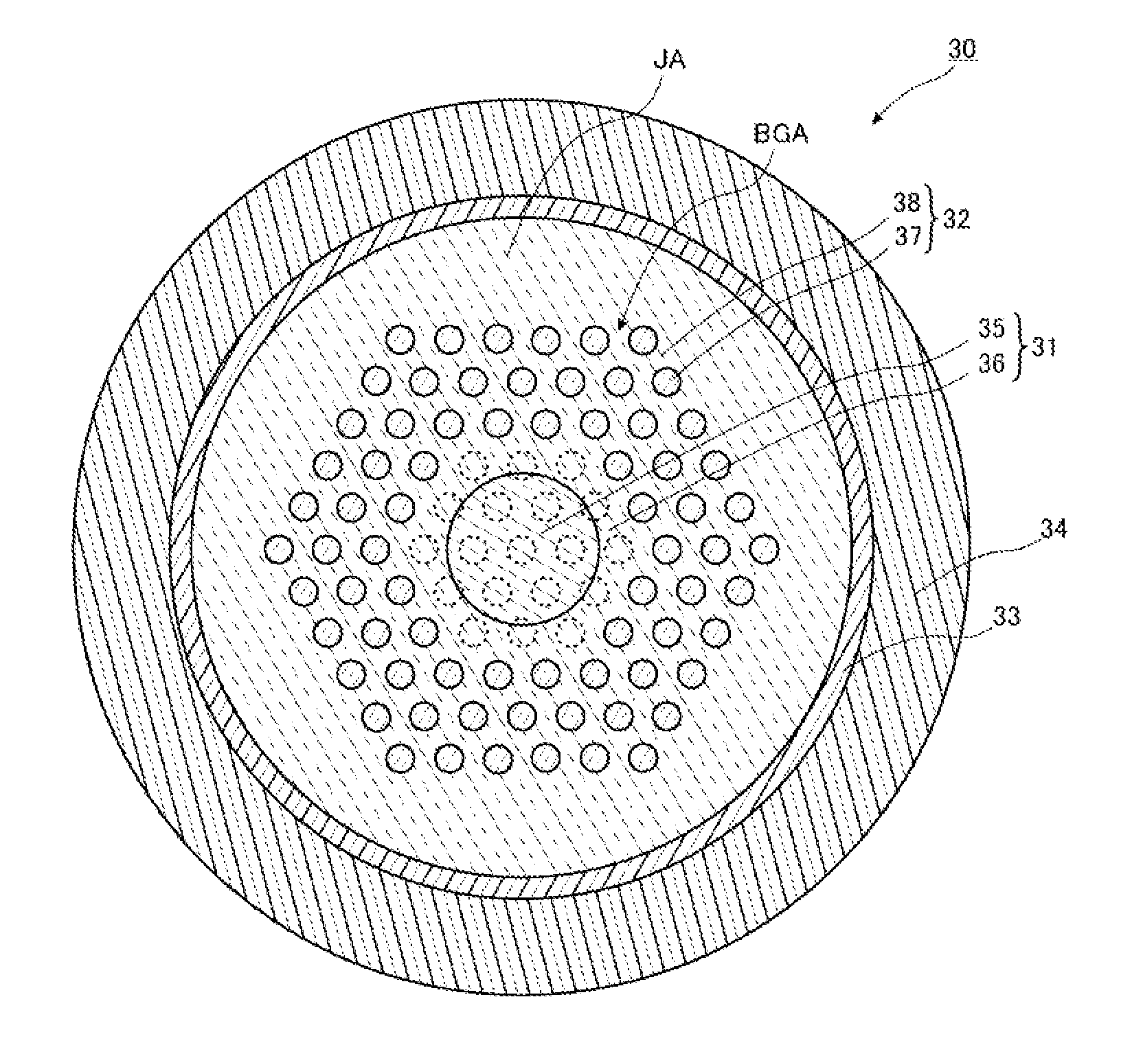
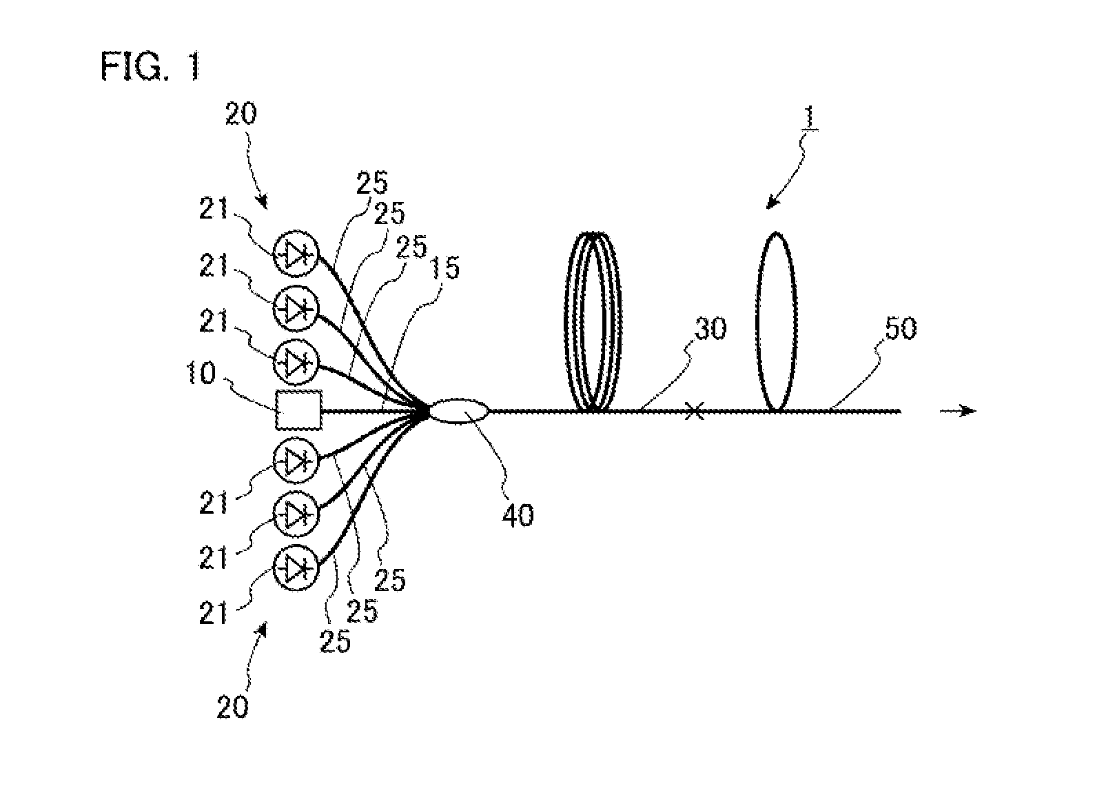
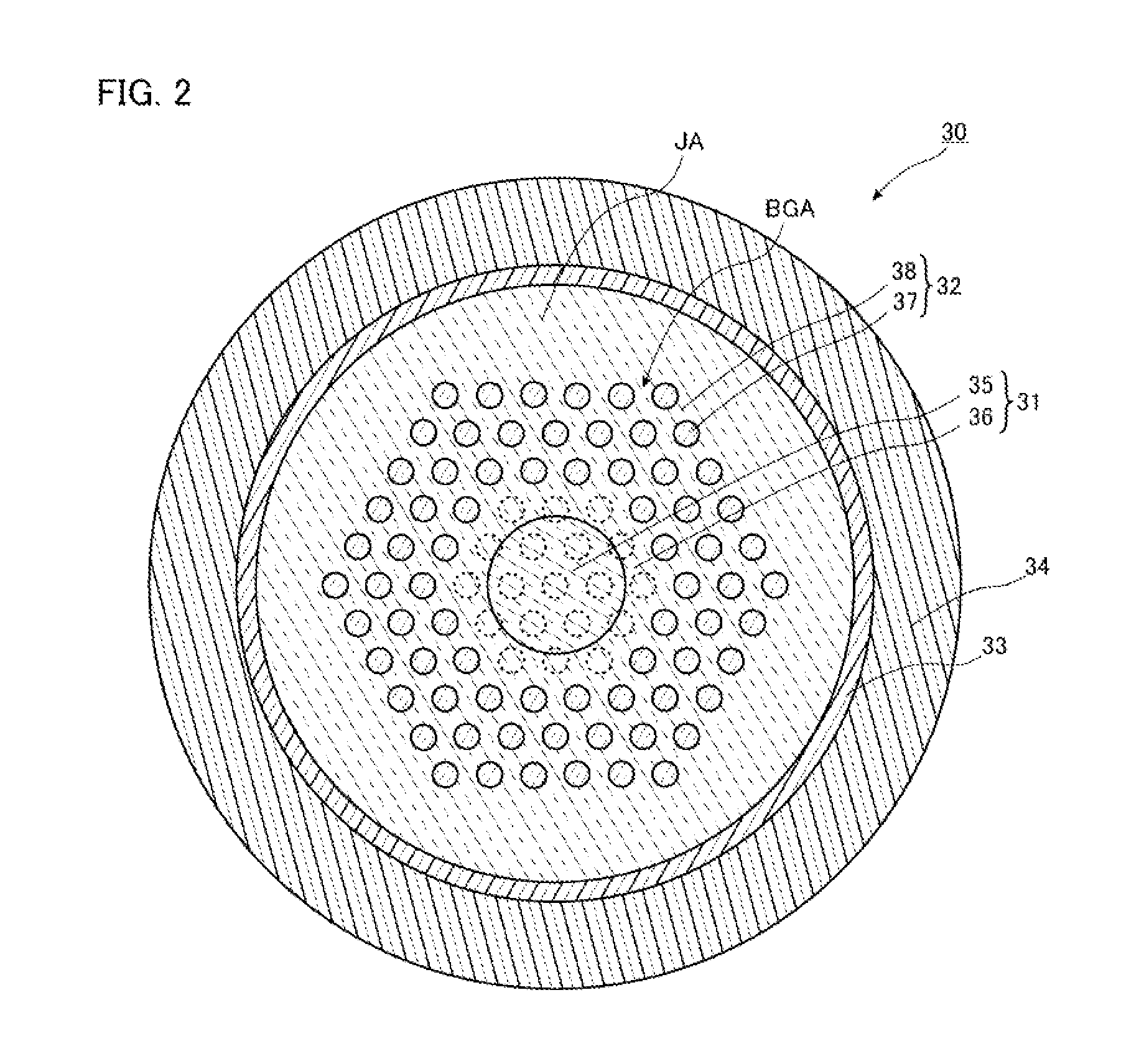
[0028]FIG. 1 is a diagram of a fiber laser device according to this embodiment. As depicted in FIG. 1, a fiber laser device 1 includes a seed light source 10 that emits seed light, a pumping light source 20 that emits pumping light, an amplification optical fiber 30 to which seed light and pumping light are entered, an optical combiner 40 that joins the seed light source 10 and the pumping light source 20 to the amplification optical fiber 30, and a delivery fiber 50 whose one end is joined to the amplification optical fiber 30 as main configurations.

[0029]The seed light source 10 is configured of a laser light source formed of a laser diode, or configured of a Fabry-Perot or fiber ring fiber laser device, for example. Seed light emitted from the seed light source 10 is not limited more specifically. For example, in the case where the amplification optical fiber is doped with ytterbium as described later, laser light is at a wavelength of 1,070 nm. Moreover, the seed light source 10...

second embodiment

[0069]Next, a second embodiment of the present invention will be described in detail with reference to FIG. 7. It is noted that components the same as or equivalent to the components of the first embodiment are designated the same reference signs, and the overlapping description is omitted except the case where the description is made more specifically.

[0070]FIG. 7 is a diagram of a fiber laser device according to the second embodiment of the present invention. As depicted in FIG. 7, a fiber laser device 2 according to the embodiment includes a pumping light source 20, an amplification optical fiber 30, an optical combiner 40, an optical fiber 65 provided between the amplification optical fiber 30 and the optical combiner 40, a first FBG 61 provided on the optical fiber 65, an optical fiber 66 provided on the amplification optical fiber 30 on the opposite side of the optical fiber 65 side, a second FBG 62 provided on the optical fiber 66, and a delivery fiber 50 provided on the opti...


PUM


Abstract

There is provided a photonic bandgap fiber used in a state in which at least a part of the photonic bandgap fiber is bent at radii of 15 cm or greater and 25 cm or less. A large number of high refractive index portions 57 are disposed in a nineteen-cell core type in three layers, and a V value is 1.5 or greater and 1.63 or less. In the high refractive index portions 57, conditions are defined that a relative refractive index difference is Δ% and a lattice constant is Λμm so as to remove light in a higher mode at the bent portion as described above.

Description

TECHNICAL FIELD[0001]The present invention relates to a photonic bandgap fiber that can propagate light of great power while removing light in a higher mode and propagating light in a fundamental mode, and a fiber laser device using the same.BACKGROUND ART[0002]A fiber laser device is known as one of laser devices used in the fields of processing machines, medical devices, measurement devices, and the like. In such a fiber laser device, light emitted from an amplification optical fiber is sometimes propagated to a desired place through a delivery fiber and then emitted. The light emitted from the delivery fiber is sometimes condensed at a lens, or the wavelength of the light is sometimes converted to the short wavelength side using a wavelength conversion element. In these cases, from the viewpoint of improving light condensing properties or from the viewpoint of improving wavelength conversion efficiency, it is preferable to emit light of excellent beam quality from the delivery fi...

Claims


Application Information

Patent Timeline
Patent Type & Authority Applications(United States)
IPC IPC(8): H01S3/067G02B6/02H01S3/094H01S3/0941
CPCH01S3/06741H01S3/0941G02B6/02309H01S3/094003H01S3/0675G02B6/02323G02B6/02347H01S3/09408
Inventor KASHIWAGI, MASAHIROSAITOH, KUNIMASA
Owner THE FUJIKURA CABLE WORKS LTD
Why Eureka
Try Eureka