Active-control resonant ignition system

a resonant ignition and active control technology, applied in the direction of combustion ignition, combustion process, lighting and heating apparatus, etc., can solve the problems of conventional spark ignition system, electron avalanche, dielectric breakdown of gas between electrodes, etc., and achieve the effect of reducing the number of drawbacks and limitations

a resonant ignition and active control technology, applied in the direction of combustion ignition, combustion process, lighting and heating apparatus, etc., can solve the problems of conventional spark ignition system, electron avalanche, dielectric breakdown of gas between electrodes, etc., and achieve the effect of reducing the number of drawbacks and limitations

US20160013623A1Active Publication Date: 2016-01-14ZHENG MING

Image

  • Active-control resonant ignition system
  • Active-control resonant ignition system
  • Active-control resonant ignition system

Examples


Embodiment Construction

[0045]The following description is presented to enable a person skilled in the art to make and use the invention, and is provided in the context of a particular application and its requirements. Various modifications to the disclosed embodiments will be readily apparent to those skilled in the art, and the general principles defined herein may be applied to other embodiments and applications without departing from the scope of the invention. Thus, the present invention is not intended to be limited to the embodiments disclosed, but is to be accorded the widest scope consistent with the principles and features disclosed herein.

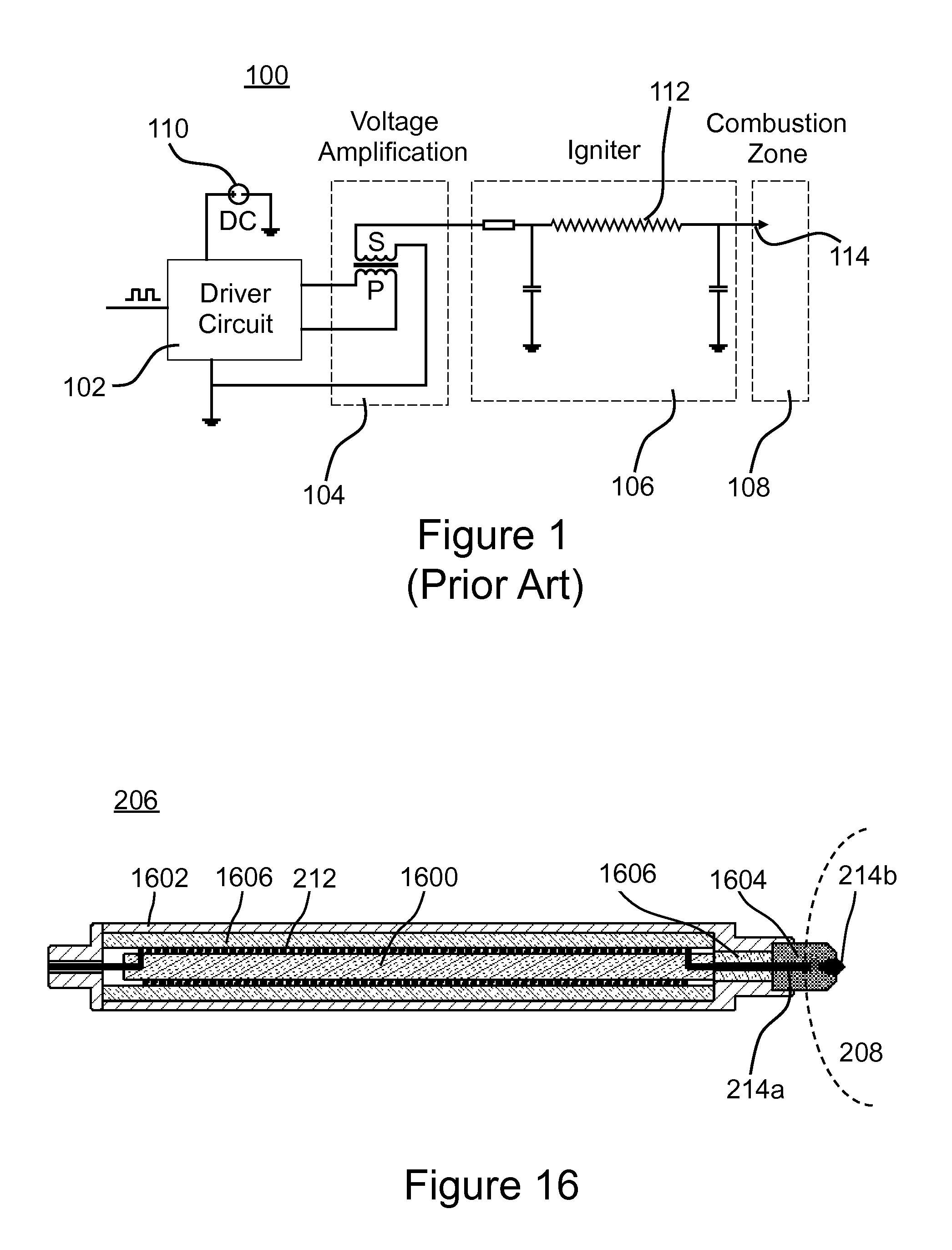
[0046]Referring now to FIG. 1, shown is a prior art corona generating system 100. The corona generating system 100 comprises a driver circuit 102, a RF transformer 104 with a primary winding P and with a secondary winding S, a resonant igniter 106, and a combustion zone 108. Driver circuit 102 is powered by a direct current (DC) source 110, and drives the prima...


PUM


Abstract

A method is disclosed for producing a corona discharge for igniting an air / fuel mixture in an internal combustion engine. An igniter is provided having a discharge tip that protrudes into a combustion zone. During a first stage of a combustion process, a first primary winding of a RF transformer is driven at a first predetermined voltage level and at a first resonant frequency that is based on a first impedance in the combustion zone prior to onset of combustion, for generating a corona discharge at the tip of the igniter. During a second stage subsequent to the first stage, a second primary winding of the RF transformer is driven at a second predetermined voltage level and at a second resonant frequency that is based on a second impedance in the combustion zone at a time that is subsequent to onset of the combustion process.

Description

FIELD OF THE INVENTION[0001]The present invention relates to systems and methods for generating and sustaining a corona electric discharge for igniting air-fuel mixtures, such as for instance in an internal combustion engine or a gas turbine.BACKGROUND OF THE INVENTION[0002]The combustion of an air-fuel mixture, for instance in an internal combustion engine (“ICE”) or a gas turbine, typically is initiated using a conventional spark ignition system. An electric arc discharge is generated in the air-fuel mixture, which heats the immediately surrounding air-fuel mixture to an extremely high temperature and causes electrons to escape from their nuclei, thereby creating a relatively small region of highly ionized gas. Combustion reaction(s) are then commenced in this small region of ionized gas. Under appropriate conditions the exothermic combustion reaction(s) heat the air-fuel mixture immediately surrounding the small region of ionized gas to cause further ionization and combustion. Th...

Claims


Application Information

Patent Timeline
14 Jan 2016
Publication
US20160013623A1
IPC
H01T19/04
CPC
H01T19/04; H01T13/44; H01T13/50; H01T15/00; F02P23/04
Inventors
ZHENG, MING; YU, SHUI