Electronic component with built-in capacitor

a technology of built-in capacitors and electronic components, which is applied in the direction of stacked capacitors, fixed capacitor details, printed circuit non-printed electric components association, etc., can solve the problems of difficult high capacitance of capacitors or capacitors, and achieve high capacitance, suppress or prevent the occurrence of improper joining or detachment of electronic components, and maintain the flexibility of flexible portions

Active Publication Date: 2016-01-14
MURATA MFG CO LTD
View PDF3 Cites 11 Cited by
  • Summary
  • Abstract
  • Description
  • Claims
  • Application Information

AI Technical Summary

Benefits of technology

[0020]In this structure, since an electronic component is able to be provided without increasing the wall thickness of the flexible portion, it is possible to use the electronic component with a built-in capacitor as a module component while maintaining the flexibility of the flexible portion. In addition, by disposing the electronic component in the thick-walled portion that is more rigid than the flexible portion, it is possible to suppress or prevent the occurrence of improper joining or detachment of the electronic component caused by deformation of the base material.
[0021]According to various preferred embodiments of the present invention, it is possible to provide an electronic component with a built-in capacitor including a capacitor having high capacitance.

Problems solved by technology

In the flexible printed circuit board in Japanese Unexamined Patent Application Publication No 7-336005, it may be difficult for the capacitor or capacitors to have high capacitance because it is difficult to increase an opposing area between the conductor patterns and the upper electrode or the upper electrodes (opposing area of the conductor pair or conductor pairs) without increasing the size of the flexible printed circuit board in plan view.

Method used


Image

  • Electronic component with built-in capacitor
  • Electronic component with built-in capacitor
  • Electronic component with built-in capacitor

Examples


first preferred embodiment

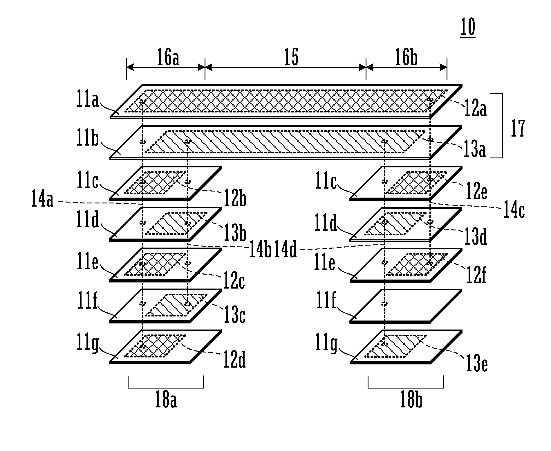
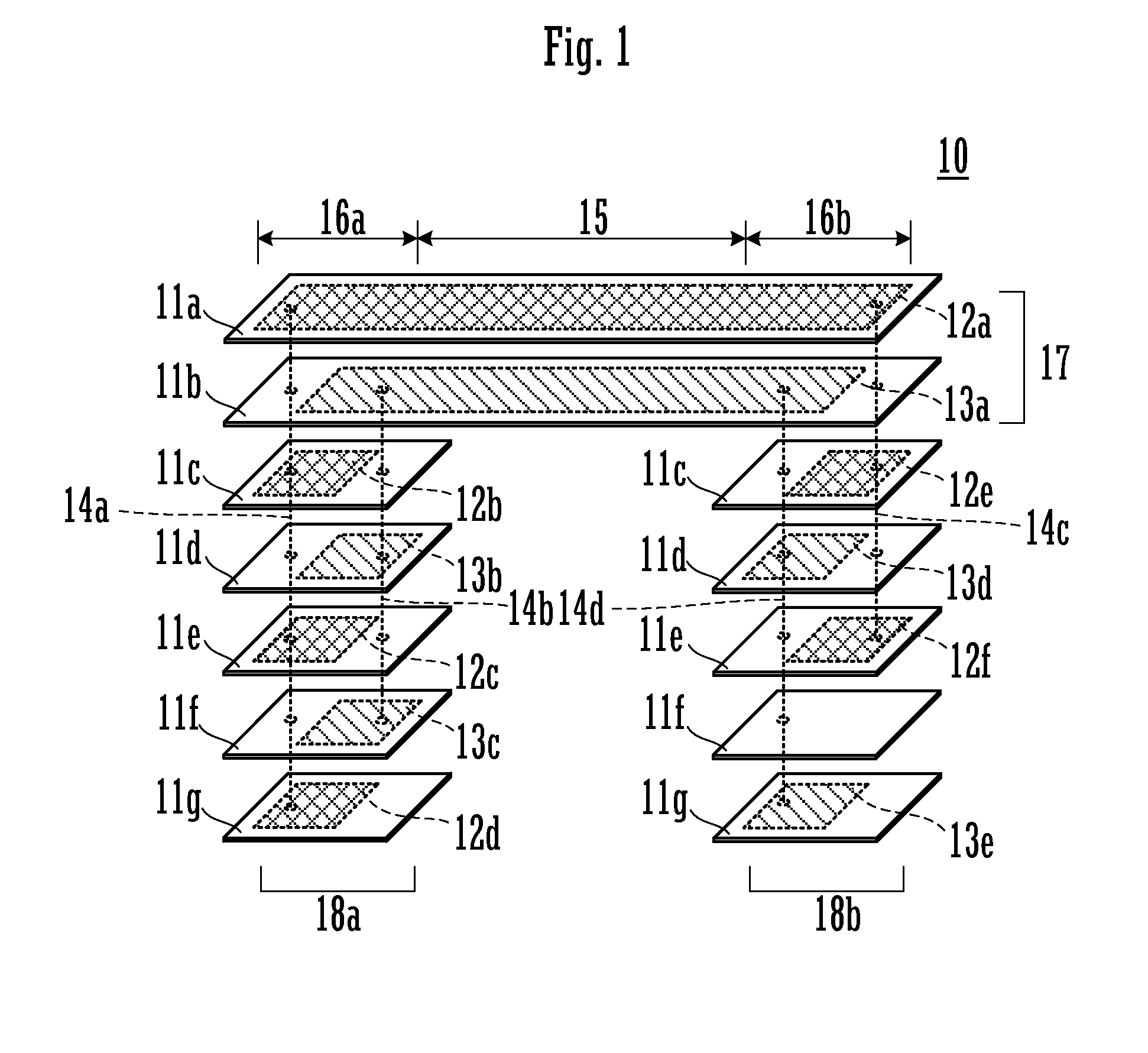
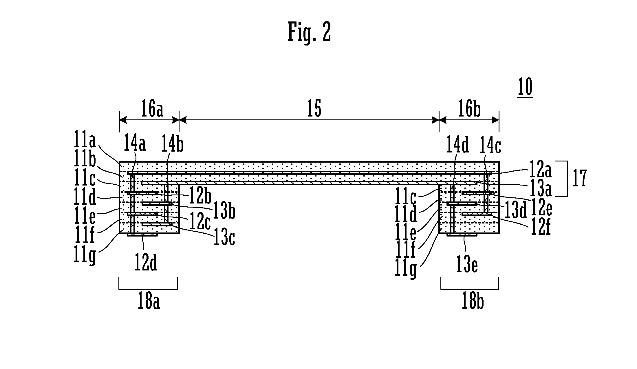
[0039]A capacitor element 10 according to a first preferred embodiment of the present invention is described. The capacitor element 10 is an example of an electronic component with a built-in capacitor according to a preferred embodiment of the present invention. FIG. 1 is an exploded perspective view of the capacitor element 10. FIG. 2 is a sectional view of the capacitor element 10. The capacitor element 10 includes flexible base material layers 11a to 11g, rectangular or substantially rectangular flat conductor patterns 12a to 12f, rectangular or substantially rectangular flat conductor patterns 13a to 13e, and via conductors 14a to 14d. The flexible base material layers 11a to 11g are each preferably made of, for example, thermoplastic resin, such as liquid crystal polymer (LCP). The conductor patterns 12a to 12f and the conductor patterns 13a to 13e are each preferably made of, for example, a metallic film, such as a copper foil.

[0040]With the flexible base material layer 11a b...

second preferred embodiment

[0069]An LC composite element 30 according to a second preferred embodiment of the present invention is described. The LC composite element 30 is an example of an electronic component with a built-in capacitor. FIG. 5 is an equivalent circuit diagram of the LC composite element 30. By connecting a coil L1 and a capacitor C1 in parallel between an external connection terminal P1 and an external connection terminal P2, an LC parallel resonant circuit is provided. That is, an LC circuit includes the coil L1 and the capacitor C1. By subjecting the LC composite element 30 to shunt-connection, it is possible to use the LC composite element 30 as a band-pass filter, for example.

[0070]FIG. 6 is an exploded perspective view of the LC composite element 30. FIG. 7 is a sectional view of the LC composite element 30. The LC composite element 30 includes flexible base material layers 31a to 31f, conductor patterns 32a to 32d, conductor patterns 33a to 33d, a conductor pattern 34, and via conducto...

third preferred embodiment

[0079]An LC composite element 40 according to a third preferred embodiment of the present invention is described. The LC composite element 40 is an example of an electronic component with a built-in capacitor. FIG. 8 is an equivalent circuit diagram of the LC composite element 40. By a coil L1 and capacitors C1 and C2, a π low-pass filter including external connection terminals P1 and P2 is provided. That is, by the coil L1 and the capacitors C1 and C2, an LC circuit is provided.

[0080]FIG. 9 is an exploded perspective view of the LC composite element 40. FIG. 10 is a sectional view of the LC composite element 40. The LC composite element 40 includes flexible base material layers 41a to 41f, conductor patterns 42a, 42b, 43a, 43b, 44a, 44b, 45a, 45b, 46, and 47a to 47d, and via conductors 14.

[0081]With the flexible base material layer 41a being the uppermost layer and the flexible base material layer 41f being the lowermost layer, the flexible base material layers 41a to 41f are stack...


PUM


Abstract

A capacitor element includes a plurality of flexible base material layers that are stacked upon each other, and conductor patterns that are provided on the flexible base material layers and that define a capacitor. The capacitor element also includes a flexible portion, and a rigid portion having a larger number of stacked flexible base material layers than the flexible portion. Conductor pattern pairs that define the capacitor are provided in both the flexible portion and the rigid portion. The conductor pattern pair that is provided in the rigid portion is connected in series with the conductor pattern pair that is provided in the flexible portion. The conductor pattern pair that is provided in the rigid portion has a larger number of tiers than the conductor pattern pair that is provided in the flexible portion.

Description

BACKGROUND OF THE INVENTION[0001]1. Field of the Invention[0002]The present invention relates to an electronic component with a built-in capacitor including a plurality of base material layers that are stacked upon each other.[0003]2. Description of the Related Art[0004]Hitherto, electronic components with a built-in capacitor including a plurality of base material layers that are stacked upon each other have been known (refer to, for example, Japanese Unexamined Patent Application Publication No. 7-336005). Japanese Unexamined Patent Application Publication No. 7-336005 discloses a flexible printed circuit board including a plurality of base material layers that are stacked upon each other and a plurality of conductor patterns that extend in straight lines and that are disposed adjacent to each other in the same layer. In the flexible printed circuit board, at one end portion of the conductor patterns, an upper electrode is provided so as to oppose the conductor patterns with a die...

Claims


Application Information

Patent Timeline
Patent Type & Authority Applications(United States)
IPC IPC(8): H05K1/18H03H1/00H03H7/01H05K1/02H05K7/02
CPCH05K1/189H05K1/0298H05K1/184H05K7/023H03H7/0115H03H2001/0021H05K2201/042H05K2201/10015H05K2201/1003H05K2201/10098H03H1/00H01G4/30H01G4/40H05K1/162H05K1/165H05K3/4691H01G4/228H05K1/148H03H2001/0085H05K2201/09263
Inventor KATO, NOBORU
Owner MURATA MFG CO LTD
Why Eureka
Try Eureka