
Silicon wafer slicing device using wire discharge machining

a technology of machining and silicon wafers, which is applied in the direction of electrical-based machining electrodes, manufacturing tools, electrolysis components, etc., can solve the problems of high cost and large amount of silicon wafers, and achieve the effects of reducing damage rate, increasing the production amount of silicon ingots, and improving surface roughness

Active Publication Date: 2016-01-21
KOREA INST OF ENERGY RES
View PDF2 Cites 6 Cited by
  • Summary
  • Abstract
  • Description
  • Claims
  • Application Information

AI Technical Summary

Benefits of technology

The present invention provides a silicon wafer slicing apparatus using wire discharge machining that can reuse or recycle wires, prevent wastes, and decrease damage to the wafer during the fabrication process. By performing arc discharge machining and electrolysis machining at the same time, the surface roughness of the wafer is improved. Additionally, using this method, a wafer with a thickness not greater than 100 μm can be fabricated, increasing the production amount per silicon ingot while decreasing damage during the cutting process.

Problems solved by technology

By the way, this method requires a lot of money for preparing the wire and the cutting oil and for performing the coating, and it also generates a massive amount of environmental contamination wastes such as silicon carbide or ethylene glycol, which makes a silicon wafer manufacturing a high cost process.

Method used


Image

  • Silicon wafer slicing device using wire discharge machining
  • Silicon wafer slicing device using wire discharge machining
  • Silicon wafer slicing device using wire discharge machining

Examples


Embodiment Construction

[0026]The terms and words used in the specification and claims are not to be construed to be limited by typical or lexical meanings, but to be construed by meanings and concepts coinciding with technical spirits of the present invention based on a principle that an inventor can adequately define a concept of a term in order to describe his / her invention in the most suitable way. Also, since the embodiments set forth in this specification and the configuration illustrated in the appended figures only represent preferred embodiments and do not encompass all technical spirits of the present invention, it is to be appreciated that there can be various equivalents and modifications which can replace them at the time of filing.

[0027]Silicon is a semiconductor having an extremely low electrical conductivity. Therefore, a silicon ingot has been regarded as not proper for discharge machining; however it is known recently that an arc discharge can be performed on the silicon by using DC, high...


PUM

PropertyMeasurementUnit
peak voltageaaaaaaaaaa
sustaining timeaaaaaaaaaa

Abstract

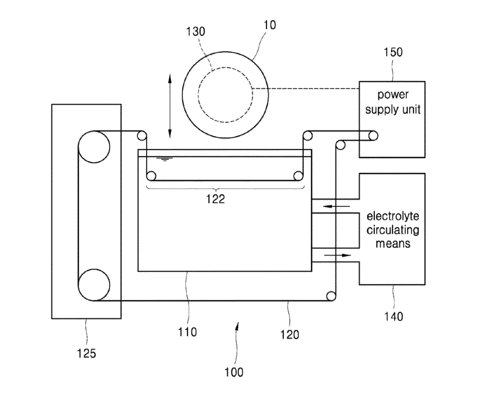
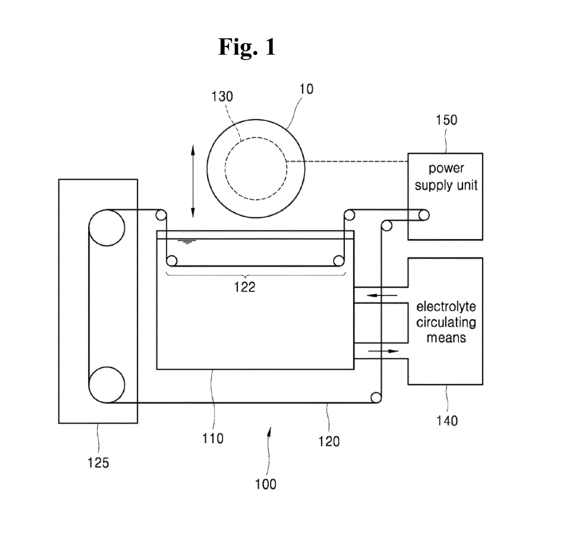
Disclosed is a wafer slicing apparatus which cuts a silicon ingot to fabricate a silicon wafer, and more specifically, a silicon wafer slicing apparatus cutting the silicon ingot using wire discharge machining is disclosed. The present invention provides a silicon wafer slicing apparatus using wire discharge machining comprising: a water tank which contains an electrolyte; a cutting wire which has a cutting section dipped into the water tank and is transferred by a wire driving means; an ingot transferring unit which includes an electrode on which a silicon ingot, an object to be cut, is fixed, and moves the silicon ingot up and down within the cutting section of the cutting wire; an electrolyte circulating means which circulates and refines the electrolyte stored in the water tank; and a power supply unit which supplies a source voltage to the electrode of the ingot transferring unit and the cutting wire.

Description

CROSS-REFERENCE TO RELATED APPLICATION[0001]This application claims the benefit of Korean Patent Application No. 10-2014-0090083, filed on Jul. 16, 2014 in the Korean Intellectual Property Office, the disclosure of which is incorporated herein in its entirety by reference.BACKGROUND[0002]1. Technical Field[0003]The present invention relates to a wafer slicing apparatus which cuts a silicon ingot to fabricate a silicon wafer, and more specifically, to a silicon wafer slicing apparatus which cuts the silicon ingot using wire discharge machining.[0004]2. Description of the Related Art[0005]In order to fabricate a silicon ingot, a mechanical method, which sprays a slurry containing an abrasive (silicon carbide particles) mixed with cutting oil on a wire and cuts the silicon ingot by a friction between sprayed particles and the silicon ingot, or coats the wire with the abrasive, and rubs the coated wire against the silicon ingot to cut the silicon ingot, is used to fabricate a wafer.[000...

Claims


Application Information

Patent Timeline
Patent Type & Authority Applications(United States)
IPC IPC(8): B23H7/08B23H5/02B23H7/36
CPCB23H7/08B23H7/36B23H5/02B23H9/00B23H7/02B23H7/04
Inventor JANG, BO-YUNCHOI, SUN-HOSONG, HEE-EUN
Owner KOREA INST OF ENERGY RES
Learn More