
Free space optical communication system

a communication system and optical communication technology, applied in the field of optical communication systems, can solve the problems of high cost of a photomultiplier detector, difficult use of a single detector receiver, and inability to meet the needs of a large number of users, so as to improve the frame rate, increase the frame rate, and improve the frame rate

Active Publication Date: 2016-01-21
SHILAT OPTRONICS
View PDF33 Cites 47 Cited by
  • Summary
  • Abstract
  • Description
  • Claims
  • Application Information

AI Technical Summary

Benefits of technology

The patent describes different ways to increase the frame rate of imaging arrays for optical communication systems. One method is to divide the array into smaller sub-regions with similar size to the desired target. Each sub-region contains pixels that are wired serially, allowing all pixels within the sub-region to be accessed simultaneously, rather than sequentially as in conventional arrays. This results in faster frame scanning and provides more efficient access to the desired information. Another method is to use a spot scanning process across multiple pixels or a spread wavelength technique to increase the information transfer rate. These techniques provide faster and more efficient access to the optical communication system, and can be used to achieve higher bit rates.

Problems solved by technology

A single detector receiver has a basic operational limitation that makes its use more difficult in the field, in that the field of view is very small, and thus mandates accurate alignment of the receiver with the transmitter.
However, the cost of a photomultiplier detector is high, and semiconductor detectors present a much more practical option.
The main limitation of a large area, low noise detector such as a PTM, is the quantum noise caused by the background radiation.
The use of a large numerical aperture leads to large amounts of collected background radiation and hence high quantum noise.
In addition to the quantum noise, there are several additional disadvantages of the PMT, such as its high cost, the low quantum efficiency of a photocathode based detector, and the gradual degrading of the sensitivity of the detector with use.
Such a small FOV for a free space optical communication application, would require precise alignment of the receiver with the transmitter, and is not therefore suited to tactical needs in the field.
The main limitation to realizing a free space tactical optical communication system is the strong dependence between the sensitivity of the receiver and the need for precise alignment of the receiver towards the transmitter.
Since a sensitive receiver can only be practically realized using small area detectors, but this leads to a small angular aperture, making use more problematic.
However, there is a problem with such use of a large area, high pixel count, imaging array, since such sensors are not intended for use at the high bit-rates typical of optical communication links.
But the limited frame rate of such an imaging array, generally in the range of some tens of frames per second, (though special design systems may achieve a thousand frames per second), presents a major disadvantage.
Since a conventional CCD or CMOS based imaging array operates by reading out the pixel data of the entire array column-by-column, such a conventionally constructed sensor array will be unable to provide significant improvement in the frame rate, since in order to access all of the pixels in the ROI, it will be necessary to read all of the pixels in the columns running through the ROI, and therefore, no increase in the frame rate can be achieved.

Method used


Image

  • Free space optical communication system
  • Free space optical communication system
  • Free space optical communication system

Examples


Embodiment Construction

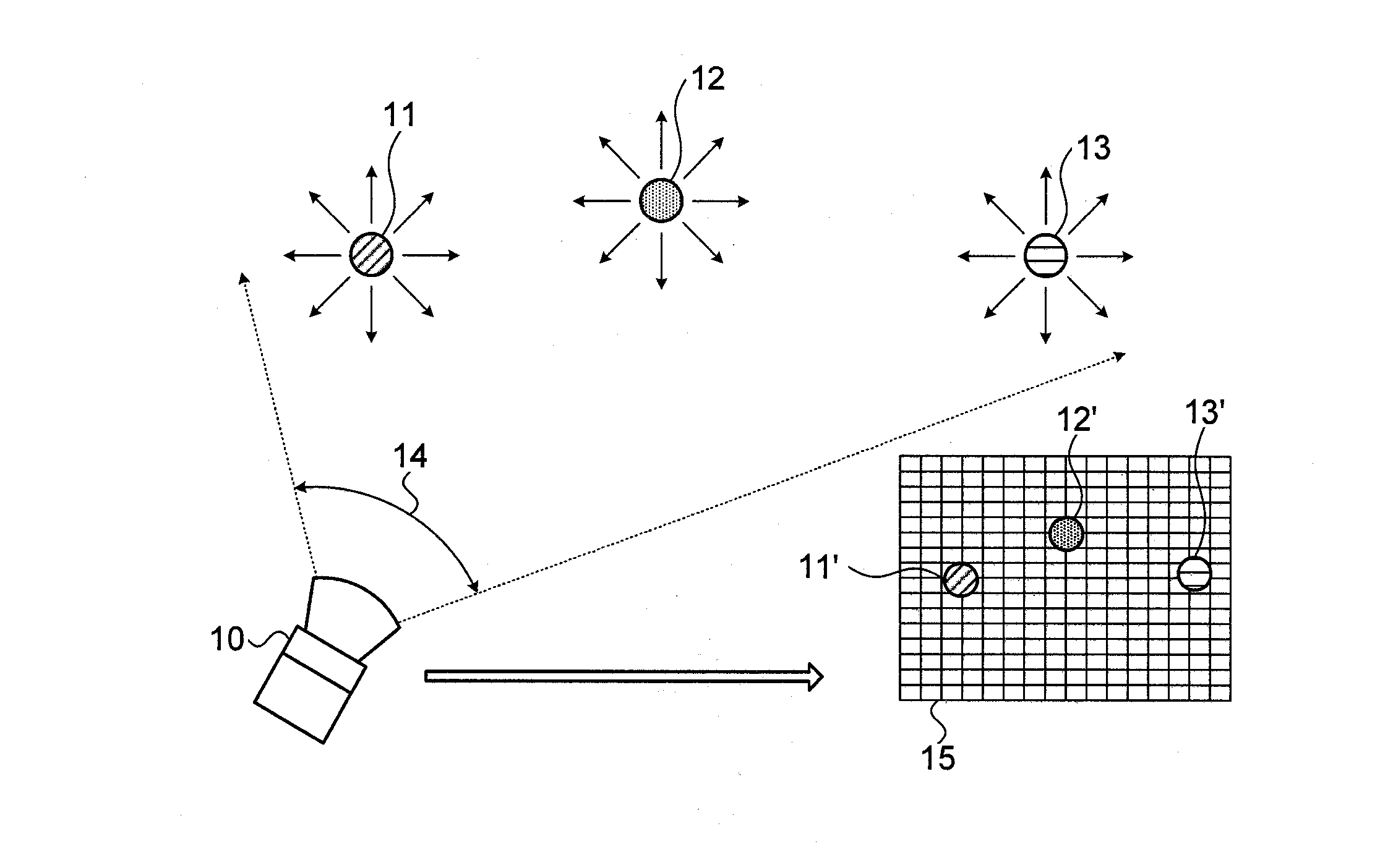
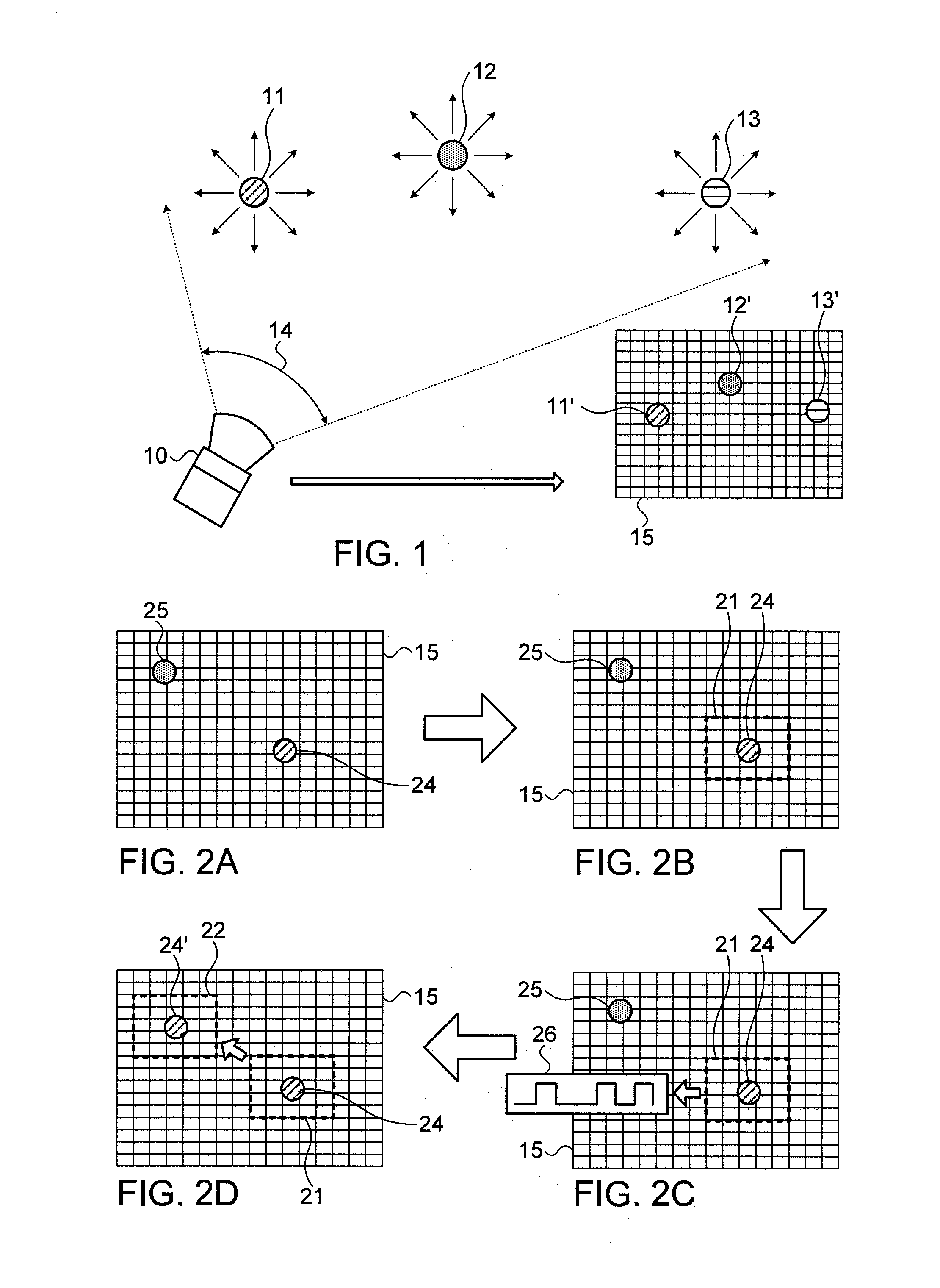
[0038]Reference is now made to FIG. 1, which illustrates schematically a scenario illustrating the way in which the receiver unit 10 of a communication system of the present application, surveils the scene in front of it over a large field of view 14, looking for transmitters whose operators may be attempting to communicate with the receiver. The transmitters will generally be light sources based on a single emitter laser diode or a laser diode array, modulated, using the serial communication signal which it is desired to transmit to the receiver. In the scenario of FIG. 1, several such transmitters 11, 12, 13, have been located in such a scan, and are imaged on the image sensor array 15 of the video camera in the receiver 10 as signal spots 11′, 12′13′, each of which could cover one or more pixels of the sensor array. Detection and identification of the transmitter sources can be performed by means of the coding and detection methods shown in International Patent Application publis...


PUM


Abstract

A method and system for optical communication between a transmitter and receiver, using a video camera to image the location of the remote transmitter. The comparatively slow frame rate of conventional detector arrays, which would limit communication rate, is overcome by reading only pixels in a region of interest around the transmission source image, and these pixels can then be read out and the communication information on them retrieved, at a frame rate much faster than that of the conventional full frame read-out. Custom wiring of the array can be used to enable implementation of this increased frame rate. Other methods of increasing communication speed using a video camera array detector include spreading the optical signal spatially along a row of pixels, and reading those pixels simultaneously in one frame, or wavelength multiplexing the optical information, and dispersing the different wavelengths onto successive pixels of the array.

Description

FIELD OF THE INVENTION[0001]The present invention relates to the field of optical communication systems in free space from point to point, especially using a camera system.BACKGROUND OF THE INVENTION[0002]Currently free space optical communication is realized using a point source as a transmitter and a single detector receiver. A single detector receiver has a basic operational limitation that makes its use more difficult in the field, in that the field of view is very small, and thus mandates accurate alignment of the receiver with the transmitter. A large angular aperture, typically of at least 5°, would make use of such a system much simpler, since it would only be necessary for the person receiving the signal to know the approximate sector in which the transmitting party is situated, instead of the need to pinpoint their location more accurately. The requirement for the transmitter to accurately aim at the receiver depends upon the need to maintain covert transmission conditions...

Claims


Application Information

Patent Timeline
IPC IPC(8): H04B10/116
CPCH04B10/116
Inventor GUETTA, AVISHAY
Owner SHILAT OPTRONICS
Learn More