

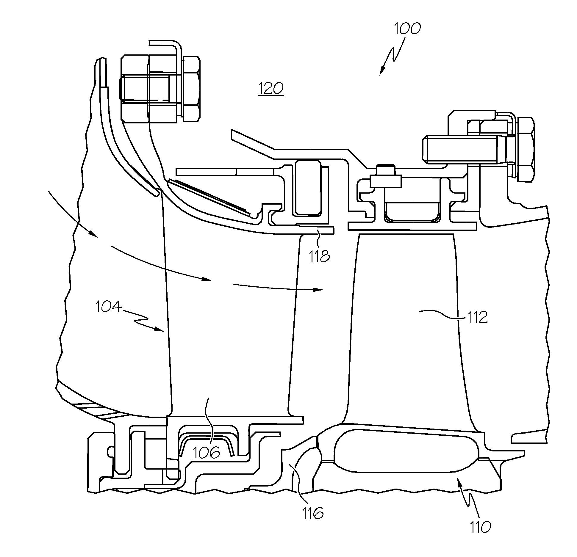
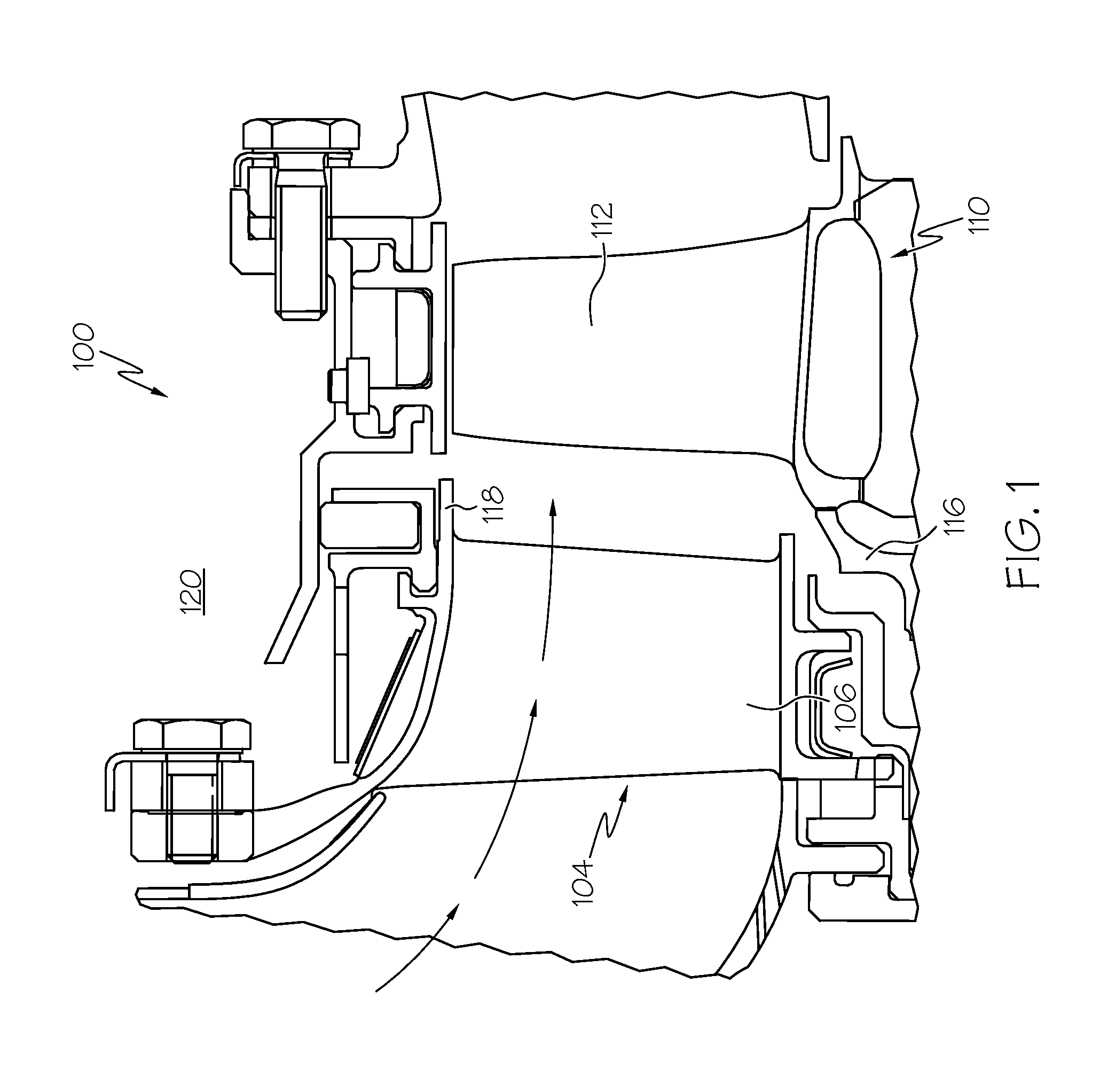
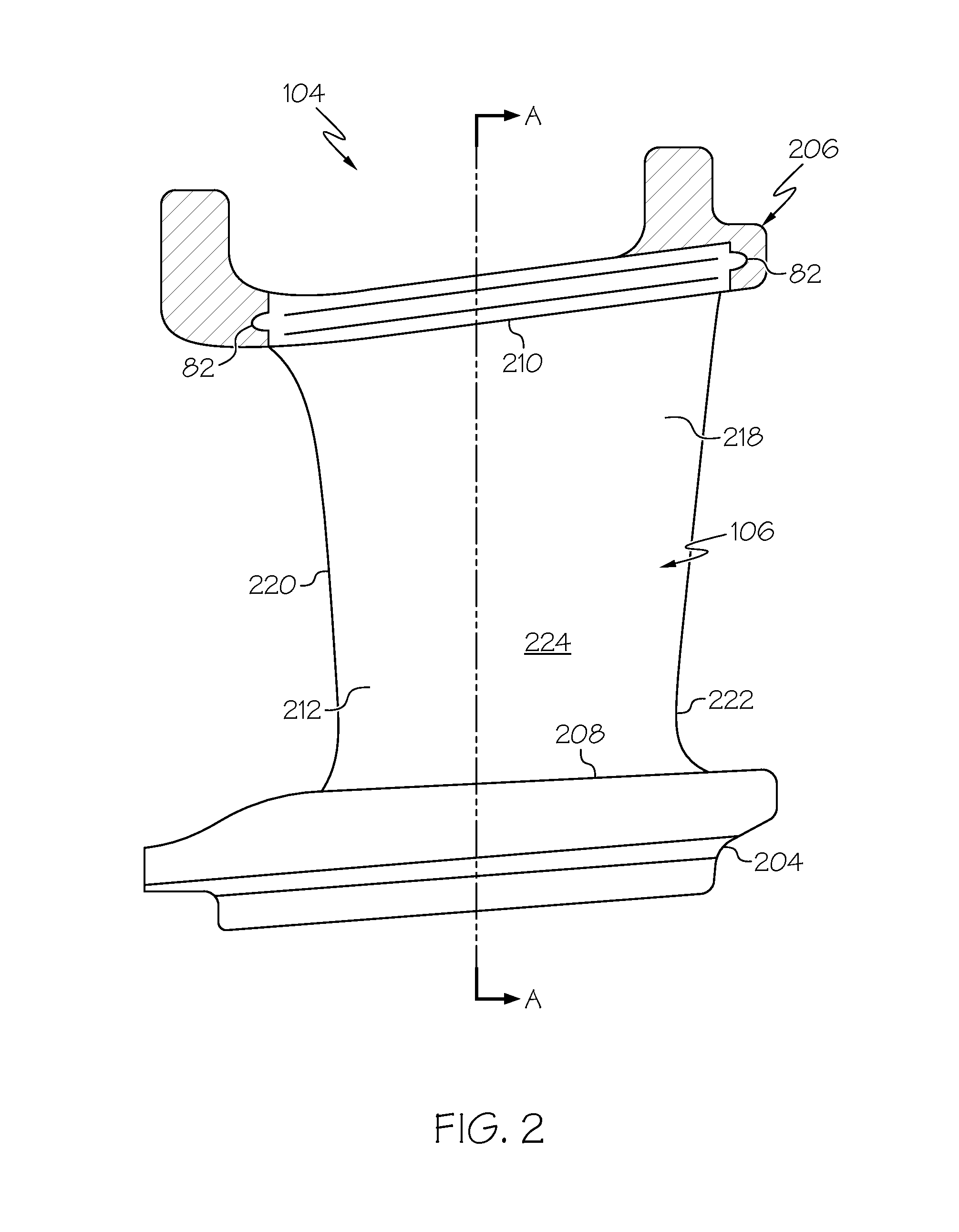
Methods for manufacturing a turbine nozzle with single crystal alloy nozzle segments
a technology of single crystal alloy and manufacturing method, which is applied in the direction of machines/engines, machine/engines, and soldering equipment, etc., can solve the problems of affecting the performance of the gas turbine engine, the segmented segmented conventional turbine nozzle may experience significant leakage, and the leakage between segments may be high, so as to minimize the leakage of combustion gas, the effect of reducing the flow of leakag
- Summary
- Abstract
- Description
- Claims
- Application Information
AI Technical Summary
Benefits of technology
Problems solved by technology
Method used
Image

Examples
Embodiment Construction
[0019]The following detailed description is merely exemplary in nature and is not intended to limit the invention or the application and uses of the invention. As used herein, the word “exemplary” means “serving as an example, instance, or illustration.” Thus, any embodiment described herein as “exemplary” is not necessarily to be construed as preferred or advantageous over other embodiments. All of the embodiments described herein are exemplary embodiments provided to enable persons skilled in the art to make or use the invention and not to limit the scope of the invention which is defined by the claims. Furthermore, there is no intention to be bound by any expressed or implied theory presented in the preceding technical field, background, brief summary, or the following detailed description.
[0020]Various embodiments are directed to methods for manufacturing a turbine nozzle with single crystal alloy nozzle segments. Such manufacturing methods enable using a single crystal alloy ma...
PUM
| Property | Measurement | Unit |
|---|---|---|
| temperature | aaaaa | aaaaa |
| speeds | aaaaa | aaaaa |
| velocity | aaaaa | aaaaa |
Abstract
Description
Claims
Application Information