Perfusion phantom device

a technology of phantom device and phantom, which is applied in the field of perfusion phantom device, to achieve the effects of reducing the risk of temporal variation of dispersion, rapid development, validation and calibration of accurate quantification methods, and reliable, reproducible and efficient simulation of myocardial perfusion

Active Publication Date: 2016-01-28
KING'S COLLEGE LONDON
View PDF3 Cites 7 Cited by
  • Summary
  • Abstract
  • Description
  • Claims
  • Application Information

AI Technical Summary

Benefits of technology

[0068]A possible confounding effect in first-pass perfusion quantification is due to bolus dispersion that occurs during the transit through the epicardial vessels to the myocardium. Even though dispersion effects cannot be completely excluded, these can be relegated to a minor role in the setup of the phantom of the invention due to: 1) the physiological design and size of the coronaries and myocardial compartments of the phantom, resulting in physiological flow and perfusion rates; 2) the fixed geometry of the coronaries (alterations of the perfusion rate are generated by changing the speed of the roller pumps downstream the imaging plane and not by alterations of the vascular geometry (stenosis); 3) the use of a continuous perfusion flow, eliminating the risk for temporal variations of dispersion due to the reflection of pressure waves. Moreover, in a particular embodiment pulsatile flow can be achieved by using a different type of pump.
[0069]The perfusion phantom of the invention allows reliable, reproducible and efficient simulation of myocardial perfusion. The availability of a direct comparison between the image data and reference values of flow and perfusion will allow rapid development, validation and calibration of accurate quantification methods.

Problems solved by technology

Furthermore, the plastics material must not bind to the contrast agent used in the scanning process since this may get trapped inside.

Method used


Image

  • Perfusion phantom device
  • Perfusion phantom device
  • Perfusion phantom device

Examples


example 1

Design of the Device

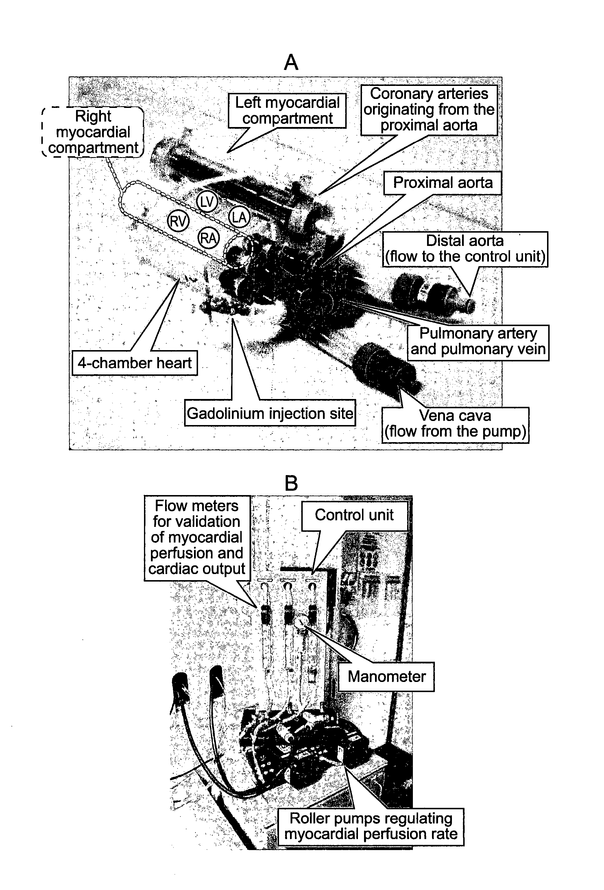
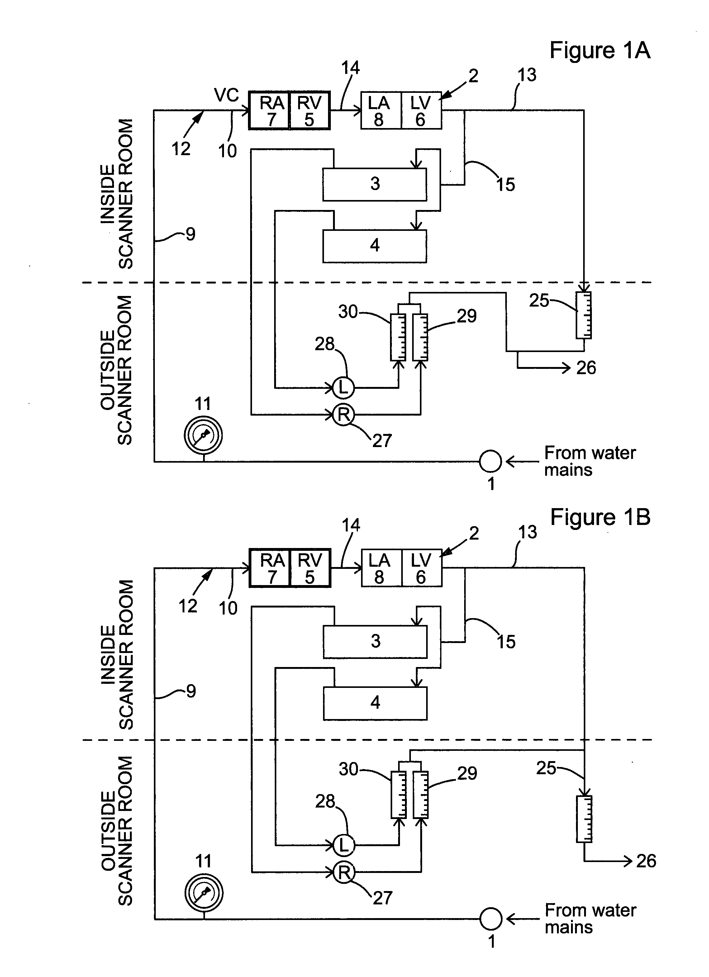
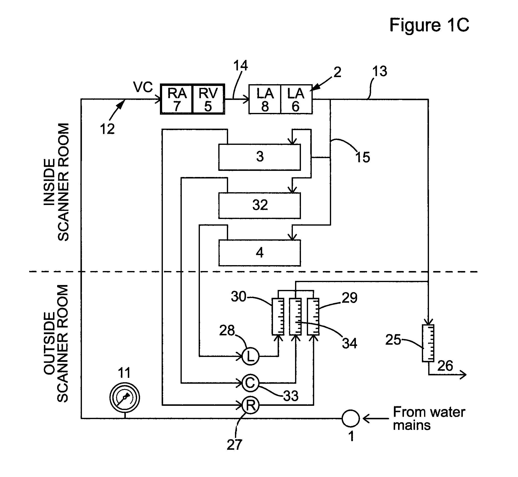
[0098]The phantom was designed to simulate dynamic of first-pass myocardial MR perfusion after the injection of a bolus of a Gadolinium-based contrast agent. The system is made up of three main parts: the main pump generating water flow in the circuits located outside the MR room, the MR-compatible unit (the phantom) located in the scanner and the control unit located outside the MR scanner room (FIGS. 1A-C and 2).

The Main Pump

[0099]The main pump (1) maintains the water flow across the phantom and was located outside the MR room indicated by the region below the dotted line in FIGS. 1A-C. Various pumps producing continuous or pulsatile flow can be fitted to the system. Alternatively, it can be driven by water pressure from a water tap, as performed in our laboratory in some preliminary experiments (data not shown). Furthermore, the system can be configured as an open or a closed circuit. In the open circuit configuration (FIGS. 1A-C), the system is continuously s...

example 2

Sensitivity to Different Contrast Agent Dose

[0118]The phantom described in Example 1 was used to assess the effects of different dosages of contrast agent on the SI of the AIF and to calculate the saturation ratio (expected peak SI / observed peak SI). Gadobutrol was injected at doses representing 0.0005, 0.001, 0.0025, 0.005, 0.01 and 0.1 mmol / kg in the following experimental conditions: cardiac output 3 L / min, right and left myocardial perfusion rate 10 mL / g / min.

[0119]To assess the effects of different dosages of contrast agent on the SI of the myocardial compartments and to calculate the saturation ratio, gadobutrol was injected at doses representing 0.001, 0.0025, 0.005 and 0.01 mmol / kg in the following experimental conditions: cardiac output 3 L / min, right and left myocardial perfusion rate 10 mL / g / min.

[0120]A progressive increase in the peak AIF SI was noted with increasing doses of Gadolinium (FIG. 5, panel A). A very low dose, equivalent to 0.0005 mmol / kg of body weight, of Ga...

example 3

Sensitivity to Myocardial Perfusion Rate

[0124]To assess the sensitivity of the system of Example 1 to different myocardial perfusion rates, first pass perfusion measurements were performed varying the perfusion rate in the L-myoc (1, 2.5, 5, 7.5 and 10 mL / g / min), in the following experimental conditions: cardiac output 3 L / min, contrast agent dosage 0.01 mmol / kg body weight.

[0125]The system showed good sensitivity for different perfusion rates, generating independent curves for the different perfusion values tested (between 1 and 10 mL / mL / min). FIG. 6 shows the time-intensity curves recorded from the aorta and the myocardial compartments for different perfusion rates.

[0126]Quantification of myocardial perfusion, provided results consistent with the gold standard perfusion measurements obtained by the phantom's flow meters. The results were as follows (deconvolution measured perfusion rate±standard deviation / actual perfusion rate): 10.4±0.4 / 10, 7.4±0.3 / 7.5, 4.7±0.1 / 5, 2.9±0.2 / 2.5, 1....


PUM


Abstract

The invention relates to a phantom device for reproducing the fluid perfusion in a body, said device comprising a phantom organ that may be introduced into a scanner, said phantom organ comprising a housing in which are defined a plurality of fluid channels, suitably of differing cross-sectional areas; a feed tube arranged to supply liquid to a first end of all of said channels and means for collecting liquid from the other end of the channels. Alternatively or additionally, the device may comprise an element comprising a phantom heart through which fluid can flow, wherein the phantom heart comprises a first chamber representing a right atrium which is arranged to receive fluid from a fluid supply, a second chamber representing a right ventricle which receives fluid leaving said first chamber, a third chamber representing a left atrium which receives fluid leaving the second chamber and a fourth chamber representing left ventricle which receives fluid leaving the third chamber; and wherein a phantom thoracic system is interposed between the second chamber and the third chamber.
Uses of the device in quality control, validation or calibration of monitoring devices such as magnetic resonance (MR) or computerised tomography (CT) scanners, in teaching or training of machine operatives or for research purposes including for research into scanners, scanning techniques or reagents such as contrast agents used in such processes, form further aspects of the invention.

Description

FIELD OF THE INVENTION [0001]The present invention relates to a perfusion phantom device that models blood perfusion in organs in the human or animal body for contrast imaging applications. In addition the invention relates to a system which relies on flow modelling in the aorta and 4-chamber heart to generate a physiological dilution curve of the contrast agent during a first pass. Uses of the device in quality control, validation or calibration of monitoring devices such as magnetic resonance (MR) or computerised tomography (CT) scanners, in teaching or training of machine operatives or for research purposes including for research into scanners, scanning techniques or reagents such as contrast agents used in such processes, form further aspects of the invention.BACKGROUND [0002]Techniques such as magnetic resonance (MR) scanning, computerised tomography (CT) scanning and ultrasound scanning are widely used diagnostic tools for a wide range of medical investigations.[0003]For insta...

Claims


Application Information

Patent Timeline
Patent Type & Authority Applications(United States)
IPC IPC(8): G09B23/28G09B23/30
CPCG09B23/303G09B23/286A61B6/583G01R33/58G01R33/56366A61B2017/00716
Inventor CHIRIBIRI, AMEDEONAGEL, EIKENOORALIPOUR, NILOUFARWESOLOWSKI, ROMAN
Owner KING'S COLLEGE LONDON
Why Eureka
Try Eureka