
Air spray painting apparatus

a technology of air spraying and spraying apparatus, which is applied in the direction of electrostatic spraying apparatus, lighting and heating apparatus, combustion process, etc., can solve the problems of satisfactory uniformity, difficulty in maintaining the viscosity of paint constant, and system of a known typ

Inactive Publication Date: 2016-03-24
EUROSIDER S DI MILLI OTTAVIO & C
View PDF8 Cites 4 Cited by
  • Summary
  • Abstract
  • Description
  • Claims
  • Application Information

AI Technical Summary

Benefits of technology

The invention is a device that reduces the need for solvents in painting, resulting in less emissions and lower costs. It uses a mixture of nitrogen / oxygen / argon that is free from humidity and hydrocarbon particles. The device also creates better paint adhesion and reduces overspray. It is suitable for traditional automatic painting systems and can be used on various types of automation markets.

Problems solved by technology

A first drawback of the systems of a known type arises in the painting step, in particular in robotized systems that use as dispensers air guns or airmix guns or rotary-bell atomizers, in particular electrostatic-painting systems.
In these systems, one of the factors that currently do not enable in all cases a satisfactory uniformity of the thicknesses of the film of paint to be achieved is the difficulty of maintaining the viscosity of the paint constant as the ambient temperature varies.
This problem imposes on the user the change of the percentages of solvents both in the case of water-based paint and in the case of solvent-based paint in order to prevent non-uniformity of the thicknesses, paint runs, and the “orange peel” effect.
Obviously, this problem also imposes machine stoppages, production rejects owing to the non-uniformity of the thicknesses, and other problems as mentioned above.
A further drawback of the known systems is represented by the fact that the compressed air used entrains along with it elements that are detrimental to a perfect distribution, penetration, and spreading of the paint on the substrates to be painted, such as for example, humidity, particles of hydrocarbons due to compression of the air, and particles in suspension present in atmospheric air.
This problem is much felt in so far as it gives rise to microbubbles that form between the substrate and the film of paint, and in time cracks may arise in the film of paint itself, with consequent problems of quality and detachment of the film itself.
From the above premises, there follow the problems typical of conventional painting that uses untreated air as carrier fluid for the atomization and sending of the spray fan onto the substrate.
Contamination of humidity, vesicular pollution of the hydrocarbon residue, as likewise oily organic substances, moreover entail as consequence the non-homogeneity of the paint applied and the unevenness of the thicknesses with consequent difficulty of spreading of the paint.
Moreover typical of electrostatic painting is formation, in the corners or at the ends of holes present in the product undergoing painting, of the Faraday-cage effect, which does not enable uniformity or perfect distribution, penetration and spreading of the paint, in certain cases causing absence of paint product, such as, for example, in the corners or on fins typical of electric motors or of heating bodies such as radiators or components of electrical household appliances and metalwork in general.
There are then known the problems in systems of painting with nanometric paints that use as thrust carrier traditional compressed air, which entrains along with it the pollutant elements (amongst which hydrocarbon particles, water particles, and pollutant dust of various nature), which render a perfect distribution, penetration, and spreading of the paint on the surfaces difficult.
In spite of all the aforesaid drawbacks, the known systems in any case use, as paint-carrier fluid, merely compressed air even thought it entrains along with it the particles of humidity, particles of oil vapours, and volatile particles present in the atmosphere, thus causing the problems listed above.

Method used


Image

  • Air spray painting apparatus
  • Air spray painting apparatus
  • Air spray painting apparatus

Examples


Embodiment Construction

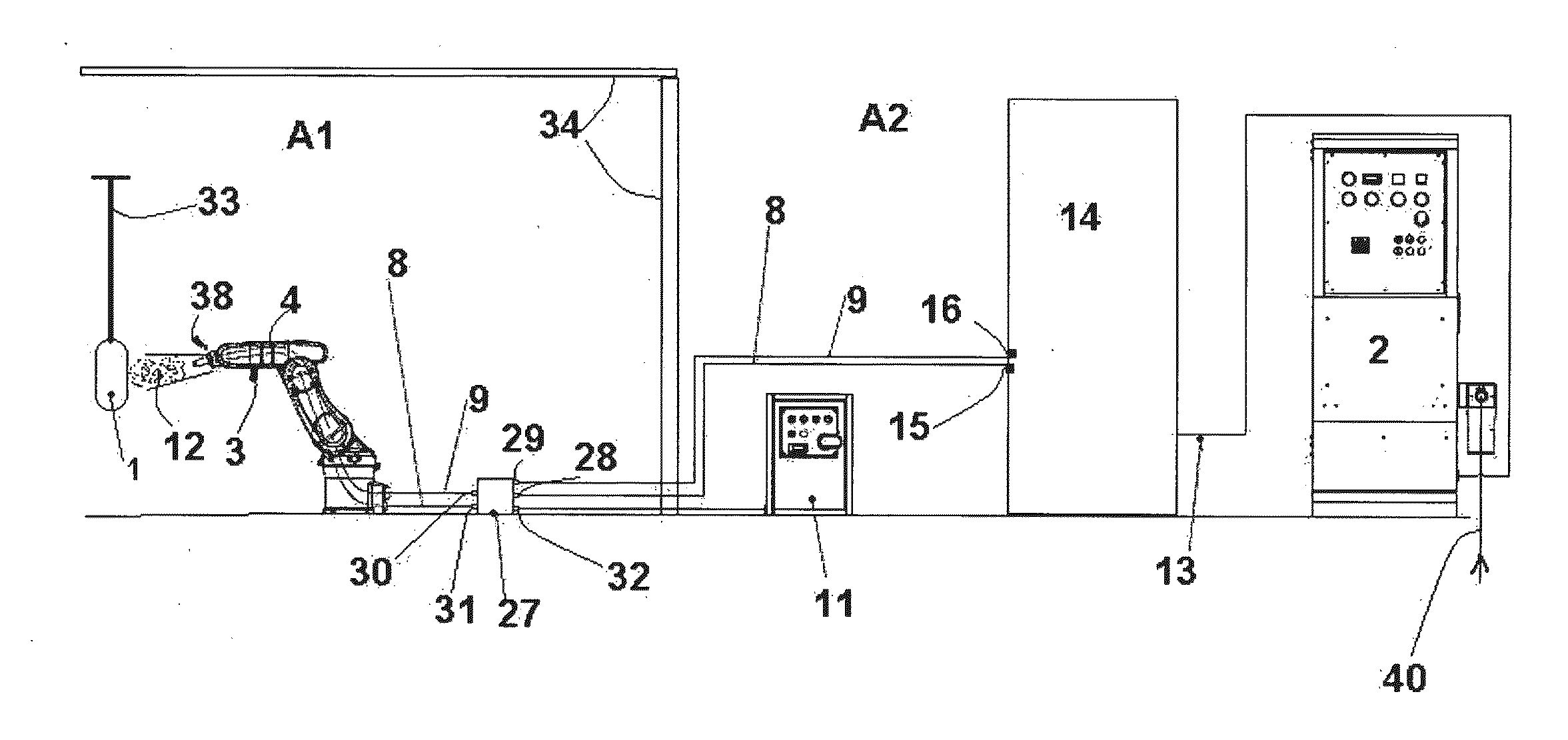
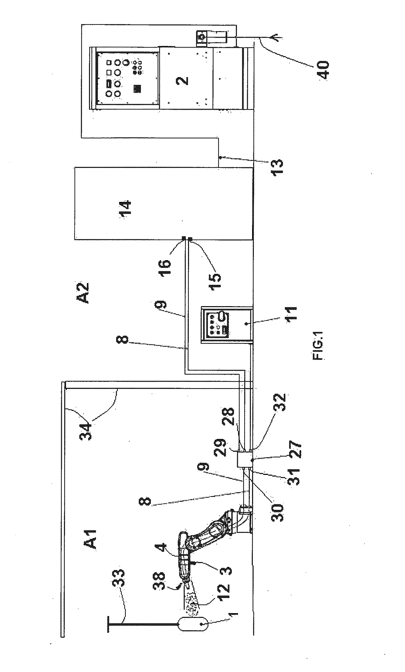
[0031]With reference to the drawings, described hereinafter is an apparatus for electrostatic painting of substrates 1 arranged in a painting area A1, for example substrates conveyed by a robotized conveying system 33 within a painting tunnel closed by walls 34 that separate it from an external area A2.

[0032]Installed in the external area A2 is a generator of carrier fluid 2, comprising, for example, hollow-fibre separation membranes and / or PSA separation systems for modifying an incoming flow 40 of compressed ambient air.

[0033]Preferably, the carrier fluid is constituted by a mixture made up of nitrogen in a range of 80-98%, oxygen in a range 1-90%, and argon in a range 1-2% obtained by continuous separation starting from a flow of compressed air taken in from the environment deprived of residual substances not comprised in the composition appearing in the table given above.

[0034]The generator 2 is operatively connected to a unit 14 for regulation and control of the pressure of the...


PUM


Abstract

An air spray painting apparatus for sending a fan of atomized paint spray via a first entrainment flow of carrier fluid and of a second flow of carrier fluid, separate from the first entrainment flow and capable of forming the spray fan, includes electrical heating elements for heating to one and the same temperature the first and second flows of carrier fluid, and a unit for regulation and control of the heating elements.

Description

SECTOR OF THE INVENTION[0001]The invention relates to an apparatus for automatic systems for air spray painting, in particular electrostatic painting with liquid paint that exploits the use of a carrier fluid constituted by air deprived of undesirable substances, together with ionization and heat conditioning of said carrier fluid.[0002]In greater detail, the invention regards a method and a painting apparatus that uses as paint-carrier fluid a mixture of modified air rich in nitrogen, oxygen, and argon continuously obtained from compressed air during painting.[0003]The operating steps of spray painting envisage in summary atomization of the paint and sending of the atomized and electrostatically charged paint onto the substrate to be painted.[0004]A first drawback of the systems of a known type arises in the painting step, in particular in robotized systems that use as dispensers air guns or airmix guns or rotary-bell atomizers, in particular electrostatic-painting systems.[0005]In...

Claims


Application Information

Patent Timeline
Patent Type & Authority Applications(United States)
IPC IPC(8): B05B5/00B05B5/03
CPCB05B5/03B05B5/001B01D53/047B01D53/22B01D2257/70B01D2257/80B01D2258/06B05B5/032B05B5/10B05B7/0815B05B7/1613B05B7/2491
Inventor MILLI, OTTAVIO
Owner EUROSIDER S DI MILLI OTTAVIO & C
Learn More