
Working machine

a working machine and base assembly technology, applied in mechanical machines/dredgers, cranes, lifting devices, etc., can solve the problems of inability to travel significant distances under their own propulsion, inability to provide a stable platform for pneumatic tires, and inability to achieve forward visibility, so as to reduce the cost of production and facilitate production. , the effect of reducing the amount of equipment/assembly chang

Inactive Publication Date: 2016-05-05
J C BAMFORD EXCAVATORS LTD
View PDF5 Cites 11 Cited by
  • Summary
  • Abstract
  • Description
  • Claims
  • Application Information

AI Technical Summary

Benefits of technology

The invention is a self-contained operating unit for a variety of different working machines that reduces the cost of production of multiple types of working machines. The base assembly is designed to improve access for servicing, reduce noise, vibration, and harshness for the operator, and improve visibility for the user. The positioning of the drive arrangement in the undercarriage allows for improved versatility and cooling of the base assembly. The use of a main chassis that is substantially the same across a variety of working machines reduces the number of parts and saves cost and time.

Problems solved by technology

Tracked excavators are not able to travel under their own propulsion for significant distances due to a low maximum speed and the damage their metal tracks cause to paved roads.
However, the working arm assembly inevitably extends forward of the superstructure during roading, which can impair ride quality, and forward visibility.
When performing working operations the pneumatic tires do not provide a stable platform, so additional stabilizer legs are required to be deployed for stability.
Whilst these components can be positioned to act as a counterbalance to forces induced during working operations, packaging constraints may force such positioning to be sub-optimal, and may also restrict sight-lines over the rear of the machine, for example.
Further, as sight-lines towards the ground close to the machine are less critical for lifting than for excavating, these are consequently quite poor.
The cost to develop different machines such as those above for different working applications is significant.
Further, the cost and delay to switch a production line from one type of machine to another is also significant.
This may be a function of the fuel efficiency of the prime mover, transmission, driveline and hydraulic system, as well as being due to secondary factors such as poor visibility meaning that an operator needs to reposition the working machine unnecessarily frequently so as to view the working operation, or carrying out an operation much more slowly, thereby compromising efficiency.

Method used


Image

  • Working machine
  • Working machine
  • Working machine

Examples


Embodiment Construction

General Format

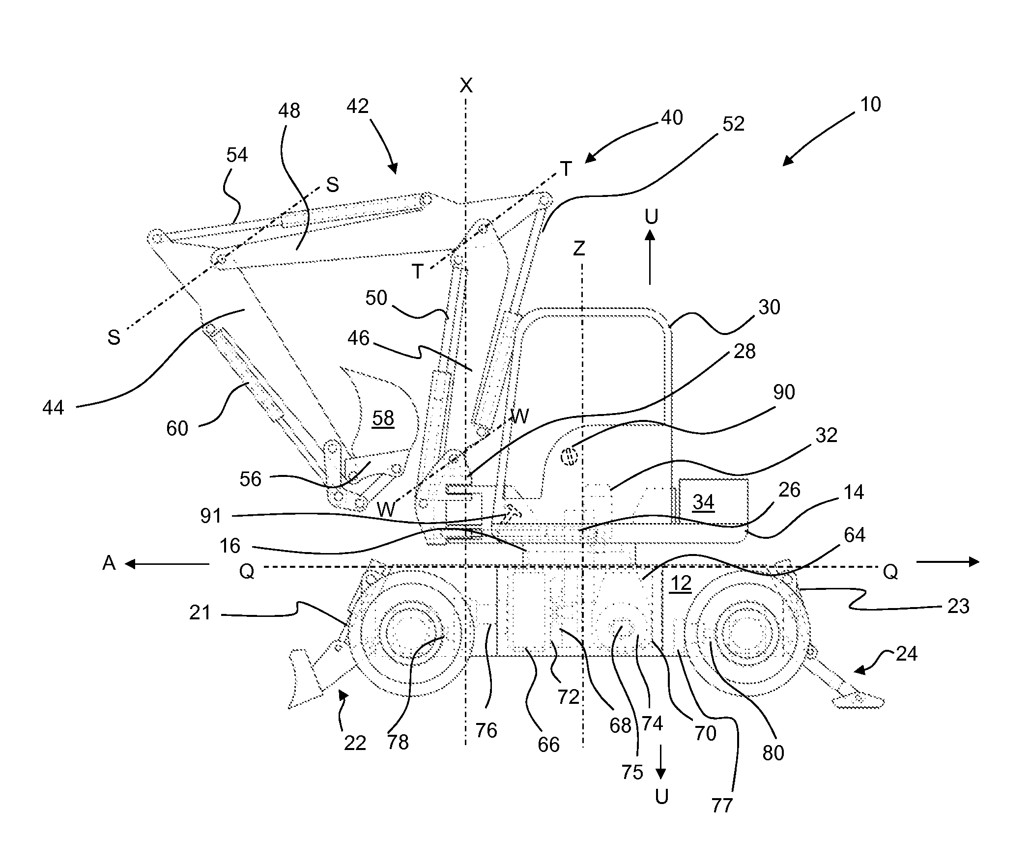
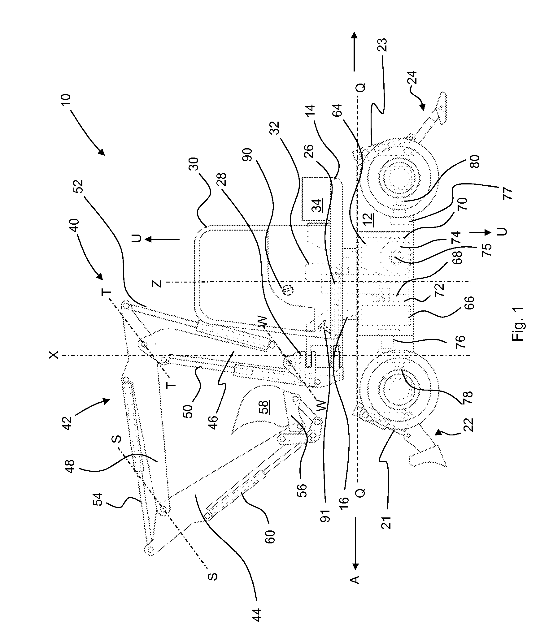
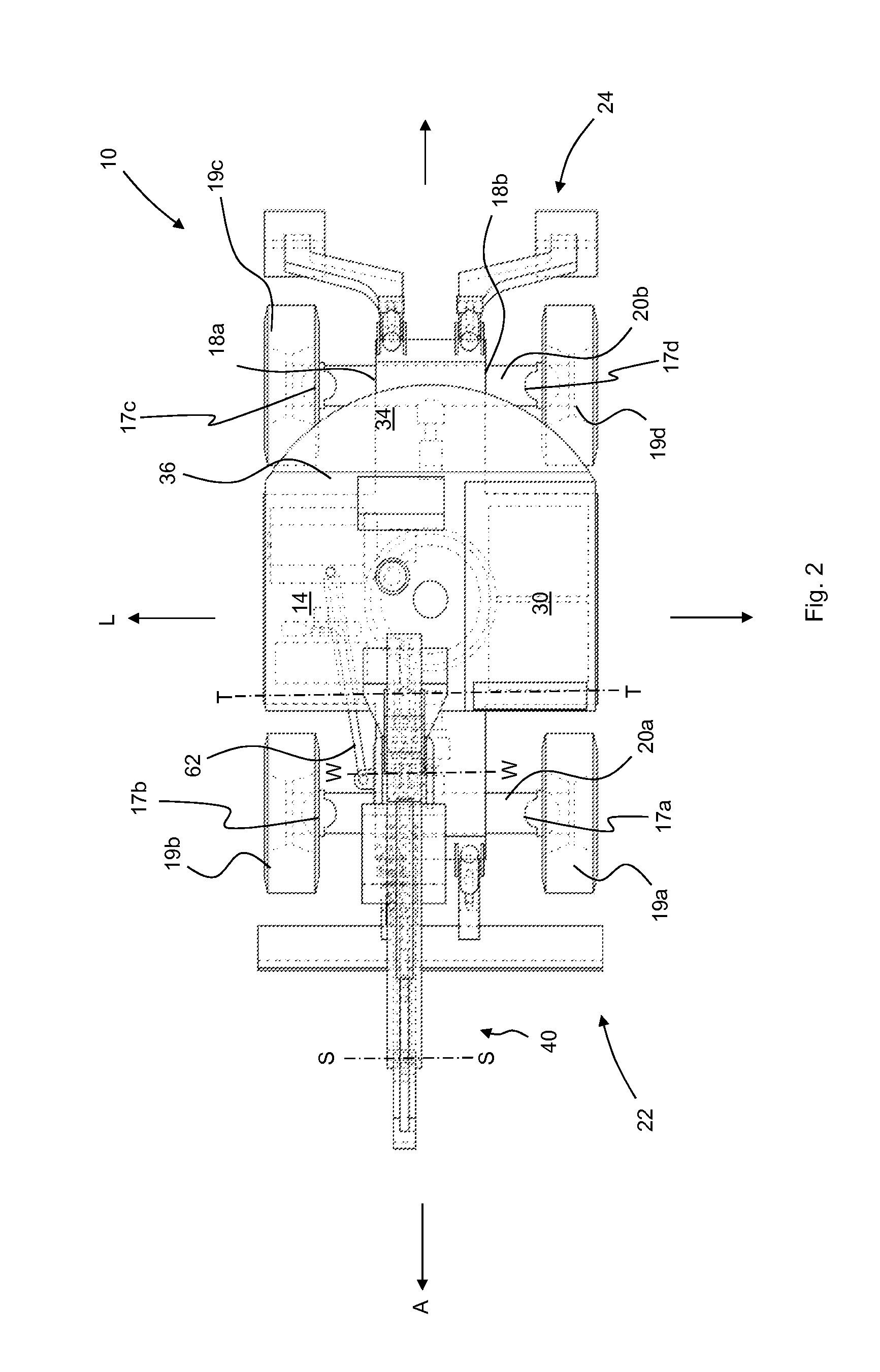
[0087]With reference to FIGS. 1 to 4, there is illustrated in somewhat simplified form a working machine 10 according to an embodiment of the present invention. In the present embodiment, the working machine may be considered to be a midi excavator (operating weight between approx. 6 and 12 metric tons). In other embodiments the working machine may be a mini excavator (operating weight between 1.2 and 6 metric tons). The machine comprises a base assembly 11 that includes an undercarriage 12. A superstructure 14 is linked to the undercarriage of the base assembly by a slewing mechanism in the form of a slewing ring 16. The slewing ring 16 permits unrestricted rotation of the superstructure relative to the undercarriage 12 in this embodiment. A cab 30 from which an operator can operate the working machine is mounted to the superstructure. A working arm arrangement 40 is rotatably mounted to the superstructure and provided for performing excavating operations.

Undercarriag...


PUM

PropertyMeasurementUnit
weightaaaaaaaaaa
weightaaaaaaaaaa
weightaaaaaaaaaa

Abstract

A base assembly for a working machine. The base assembly comprising a ground engaging structure, an undercarriage connected to the ground engaging structure, and a connector for connecting the undercarriage to a superstructure that mounts a working arm. A drive arrangement is provided for moving the ground engaging structure to propel, in use, the base assembly and a connected superstructure. The drive arrangement includes a prime mover and a transmission and the drive arrangement is housed within the undercarriage. An electronic control unit (ECU) is provided for controlling the drive arrangement and / or the ground engaging structure.

Description

FIELD OF THE INVENTION[0001]The present invention relates to a base assembly for a working machine, a working machine and / or a method of manufacturing two different working machines.BACKGROUND OF THE INVENTION[0002]Various types of working machines are known. Such machines are used typically for soil-shifting operations (e.g. trenching, grading, and loading) and materials handling (e.g. depositing aggregate in trenches, lifting materials and placing them on an elevated platform).[0003]Such machines are typically manufactured from a set of subassemblies designed specifically for one type of machine, although certain components such as engines, gearboxes, hydraulic pumps and undercarriages may be shared across different machine types.[0004]Examples of known machines include the following:[0005]Slew excavators comprise a superstructure rotatable in an unlimited fashion relative to an undercarriage. The superstructure includes a working arm arrangement for manipulating an attachment, su...

Claims


Application Information

Patent Timeline
Patent Type & Authority Applications(United States)
IPC IPC(8): B62D63/02B66F9/075E02F9/20B66C23/36B62D65/02B60K17/10
CPCB62D63/02B62D65/02B66F9/07572E02F9/2062B66C23/36B60K17/10B66F9/061B66F9/07581E02F3/42E02F9/06E02F9/2058E02F9/22B66C2700/0364E02F9/08E02F9/0858E02F3/325E02F9/006E02F9/085E02F9/121E02F9/2275E02F9/0808E02F9/0866
Inventor LYLE, JONATHANGRIFFIN, JOHNJOWETT, PETER
Owner J C BAMFORD EXCAVATORS LTD
Features
  • Generate Ideas
  • Intellectual Property
  • Life Sciences
  • Materials
  • Tech Scout
  • Unparalleled Data Quality
  • Higher Quality Content
  • 60% Fewer Hallucinations
Learn More