Method for timing a regeneration process

a regeneration process and timing technology, applied in the direction of electrical control, exhaust treatment electric control, instruments, etc., can solve the problems of increasing fuel consumption, increasing thermal wear, and engine running a bit different, so as to improve the timing of the regeneration process, increase the success rate of the regeneration, and improve the effect of the regeneration process

Active Publication Date: 2016-05-12
VOLVO LASTVAGNAR AB
View PDF14 Cites 4 Cited by
  • Summary
  • Abstract
  • Description
  • Claims
  • Application Information

AI Technical Summary

Benefits of technology

[0013]By identifying such (un)suitable time periods it becomes possible to improve the timing of the regeneration process, i.e. it becomes possible to determine in a better way when to start the regeneration. This increases the rate of success of the regeneration because it becomes possible to avoid initializing / starting a regeneration process just before a time period that, statistically, is unsuitable for regeneration, e.g. just before lunch time, and instead take the opportunity to initialize a regeneration process in the beginning of a time period that, statistically, is suitable for regeneration, even if the need for regeneration is not at its most critical level.
[0014]The inventive method thus provides a statistical prediction of time periods that are suitable and / or unsuitable for regeneration and by adapting the timing (the start) of the regeneration process as described above the rate of success of the regeneration can be increased. In turn, this means that the number of interrupted regenerations will decrease which reduces the thermal wear of the after-treatment system and prevents an unnecessary increase in fuel consumption. This is of particular importance for regeneration of units positioned further downstream than other units in the exhaust gas flow, e.g. SCR, since regeneration of such downstream units takes a longer time, perhaps around an hour.
[0025]The system for controlling the regeneration is preferably designed so that a regeneration process can be started if the need for regeneration is large even if the predicted success rate is low. This is for the purpose of avoiding a requirement for stand-still / parked regeneration which is to be avoided in some applications, for instance for city buses. On the other hand, for heavy-duty vehicles (construction equipment) it may be preferable to make use of planned stand-still / parked regeneration.
[0040]This way it is possible to adapt the regeneration time periods to different drivers who, for instance, may have lunch at different times or may run the vehicle in different ways.
[0052]Most countries have laws that regulate for how long a driver of a commercial vehicle is allowed to work before he / she must take a break. Typically, a driver may work for a couple of hours without break. Commonly, the vehicle is turned off or is allowed to operate only at a low load during such a break which means that if a regeneration process has been started when it is time for break it will be interrupted. By determining how much time that remains until such a break is expected to be taken, it becomes possible to avoid starting a regeneration process too close before the expected break. This will increase the overall success rate of the regeneration.

Problems solved by technology

Such interrupted regenerations increase the thermal wear of the after-treatment system and also lead to an increase in fuel consumption since increasing the temperature in the system normally is achieved by burning fuel either less efficiently in the engine and / or by adding it after the engine.
Further, in some cases regeneration causes the engine to run a bit different which may be undesired for the driver.
However, this does not allow an engine control system to predict the future engine load with any particularly high probability.
However, these methods are not fully satisfying if the route is not set or can be accurately predicted, or if a proper current / future driving cycle is difficult to identify or select.
It may be that the statistical data show that there is no time period suitable for regeneration.
However, on the average, the number of interrupted regenerations will decrease if the timing of the regeneration is adapted to the expected suitable and unsuitable time periods for carrying out the regeneration.
A time period unsuitable for initializing the regeneration process is just before the engine is turned off or operates at a low power, such as just before a break or the end of the working day.

Method used


Image

  • Method for timing a regeneration process
  • Method for timing a regeneration process
  • Method for timing a regeneration process

Examples


Embodiment Construction

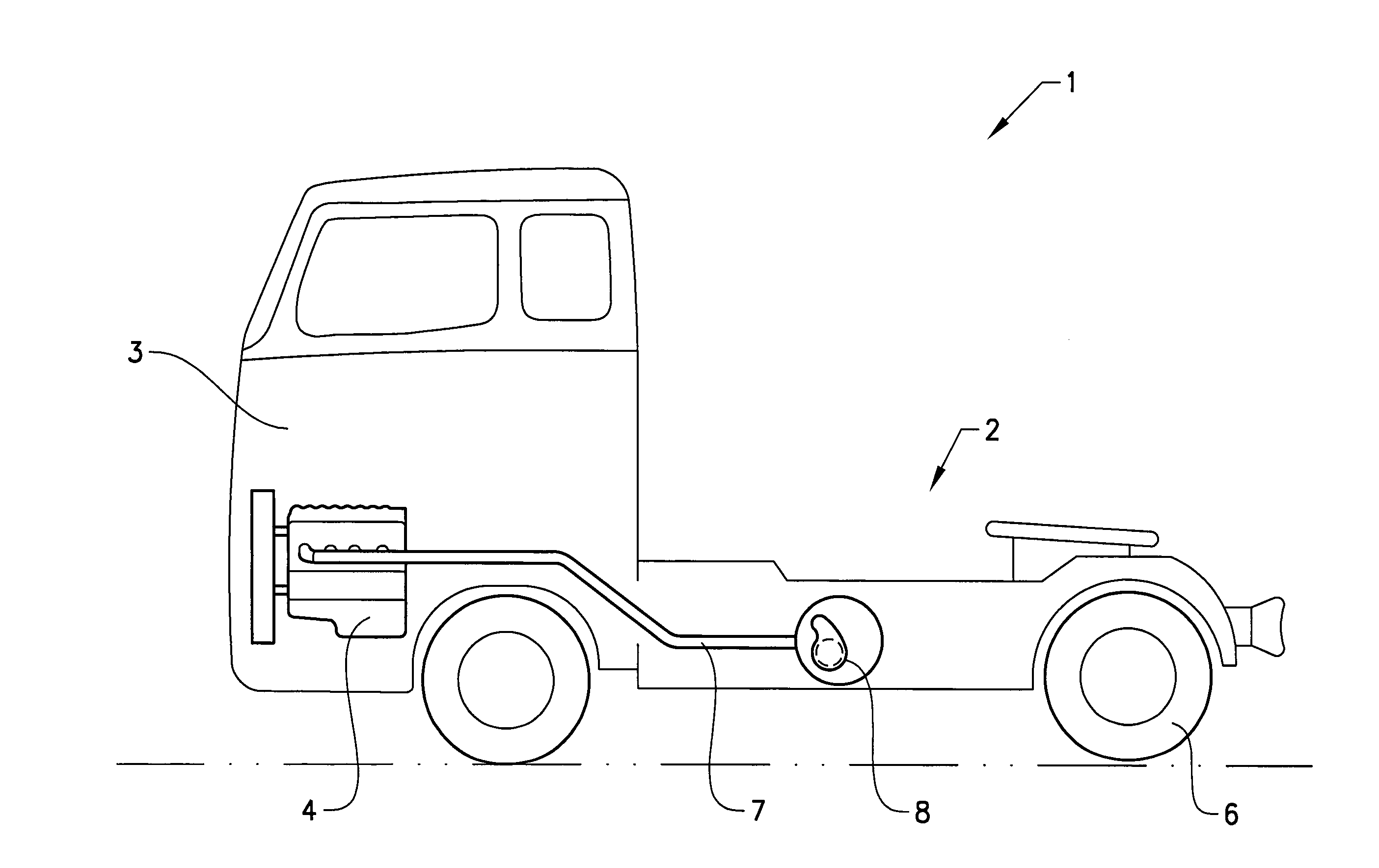
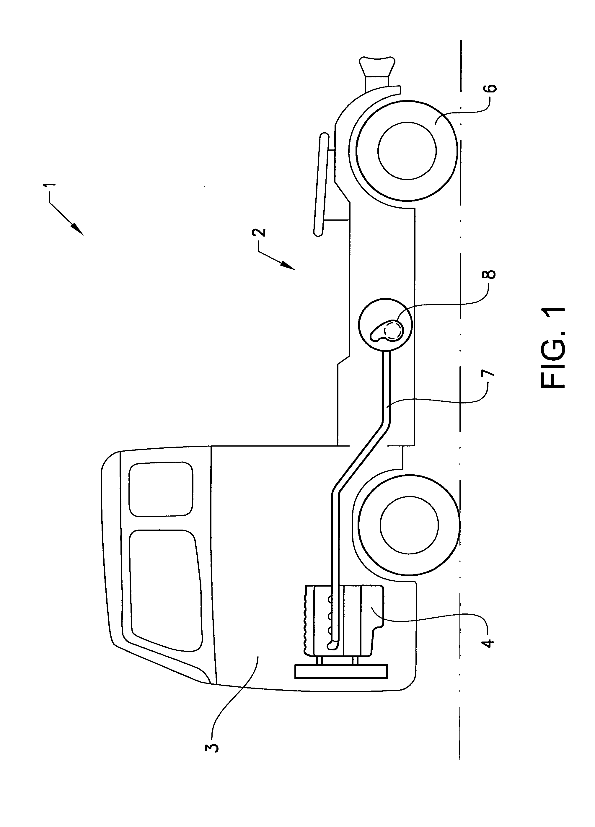
[0061]FIG. 1 shows a commercial vehicle 1 in the form of a tractor unit. The commercial vehicle 1 comprises a chassis 2 and a driver's cab 3 mounted on the chassis. Underneath the driver's cab 3 is an internal combustion engine 4, which acts on the drive wheels 6 of the commercial vehicle 1 by way of a drive train comprising a clutch and a manual transmission or an automatic transmission. The internal combustion engine 4 comprises an exhaust gas system 7 with a first muffler 8 provided with an exhaust after-treatment system (EATS) including, for instance, a diesel particulate filter (DPF) connected to a tailpipe (not shown) which expels the exhaust gases to the atmosphere.

[0062]As an example, the inventive method is applicable to a vehicle of the type shown in FIG. 1 for carrying out regeneration of the DPF.

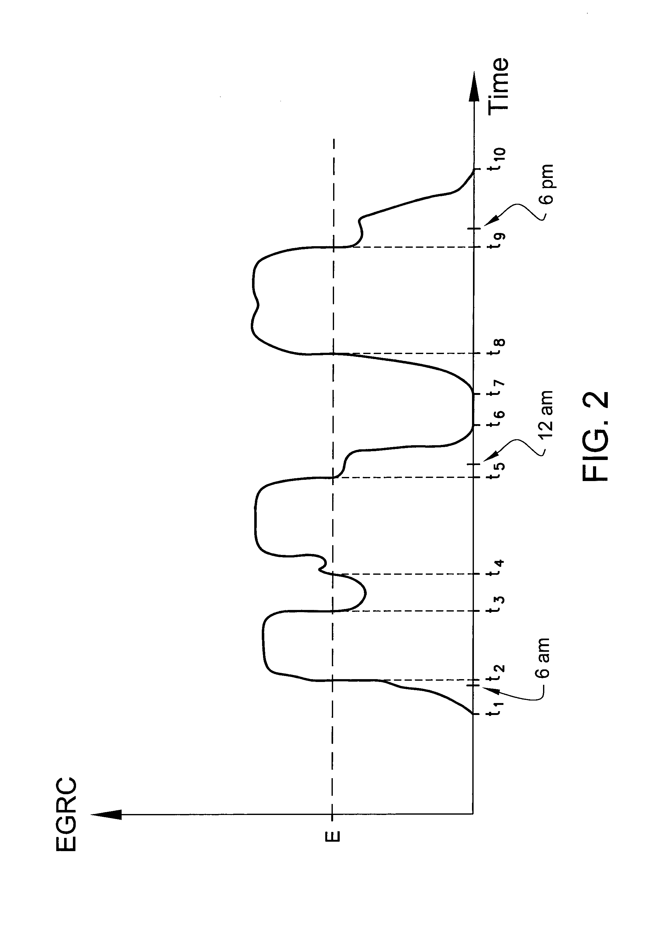
[0063]FIG. 2 shows, in a schematic view, an example of a visualized statistical probability function according to the invention. Time, as a portion of a 24-hours time period, is ...


PUM


Abstract

A method for timing of a regeneration process of an exhaust gas system of a vehicle engine includes collecting, during operation of the vehicle, data on an exhaust gas regeneration capability as a function of time, establishing, from the collected data, a statistical probability function for the exhaust gas regeneration capability as a function of time, and identifying, from the probability function, one or several time periods that statistically are suitable and / or unsuitable for carrying out a regeneration process. A method for regeneration of an exhaust gas system of a vehicle engine is also provided.

Description

BACKGROUND AND SUMMARY[0001]This invention relates to a method for timing of a regeneration process of an exhaust gas system of a vehicle engine. The invention also relates to a method for regeneration of an exhaust gas system of a vehicle engine,[0002]Exhaust gas after-treatment systems (EATSs) arranged on trucks and other vehicles normally require intermittent regeneration for removing various substances that accumulate in the system during normal operation of the vehicle and that affect the performance of the engine or the function of the after-treatment system. Examples of exhaust gas after-treatment units that may need regeneration include the following: diesel particulate filter (DPF), diesel oxidation catalyst (DOC), selective catalytic reduction unit (SCR) and urea injection system.[0003]The capability of the exhaust gas to regenerate an exhaust gas after-treatment unit is primarily dependent on the temperature and the mass flow of the exhaust gas. Regeneration is typically ...

Claims


Application Information

Patent Timeline
Patent Type & Authority Applications(United States)
IPC IPC(8): F01N9/00F01N3/023F01N11/00F01N3/20
CPCF01N9/002F01N3/2066F01N11/00F01N3/023F01N3/206F02D41/029F01N2900/0402F01N2900/0421F01N2900/0422F01N2900/08F01N2900/12F01N2900/1404F02D41/26Y02T10/40
Inventor HAMSTEN, ANDREASDAHL, JOHAN
Owner VOLVO LASTVAGNAR AB
Why Eureka
Try Eureka