Organic light emitting element

Active Publication Date: 2016-05-12
CANON KK
View PDF0 Cites 8 Cited by
  • Summary
  • Abstract
  • Description
  • Claims
  • Application Information

AI Technical Summary

Benefits of technology

[0015]The present invention has been made to solve the problems, and an object of the present invention is to provide an organic light emitting element, in

Problems solved by technology

In a blue color, however, the fact that the durability of an organic light emitting element that emits blue light is problematic and hence its continuous driving lifetime is short has been perceived as a problem.
However, the element has caused a problem from the viewpoint of luminous efficiency because the probability that a singlet exciton is produced is low as described above.
However, even when the TTA is utilized, an upper limit for the external quantum efficiency of the organic light emitting element is 12.5% and hence the efficiency can be sa

Method used


Image

  • Organic light emitting element
  • Organic light emitting element
  • Organic light emitting element

Examples


Example

Example 1

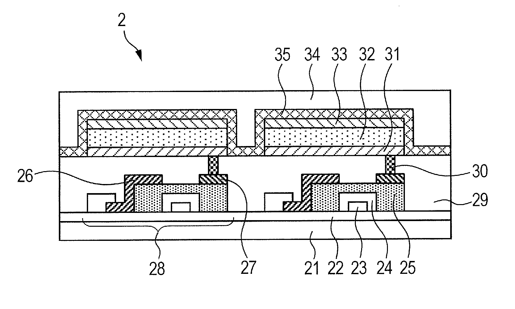
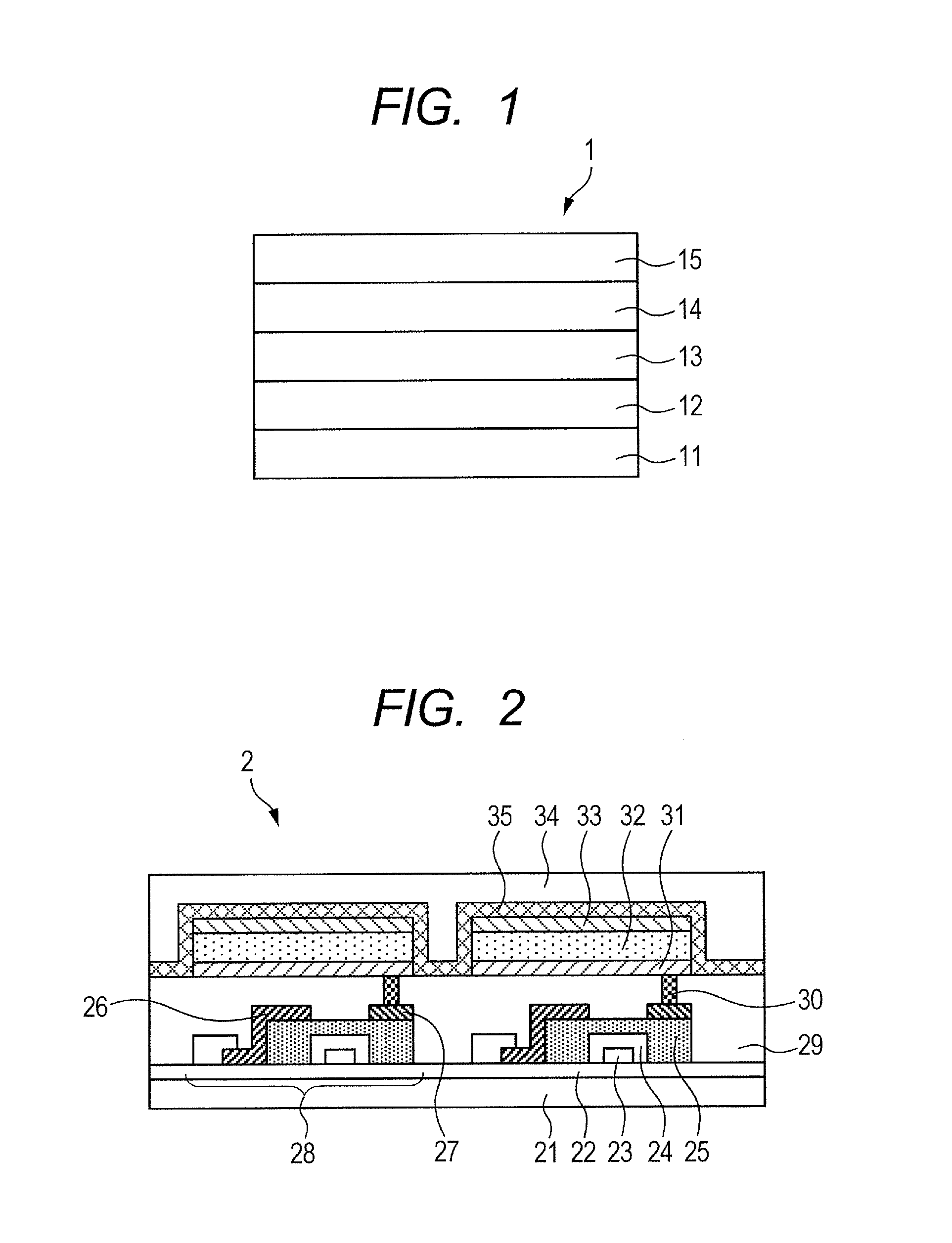
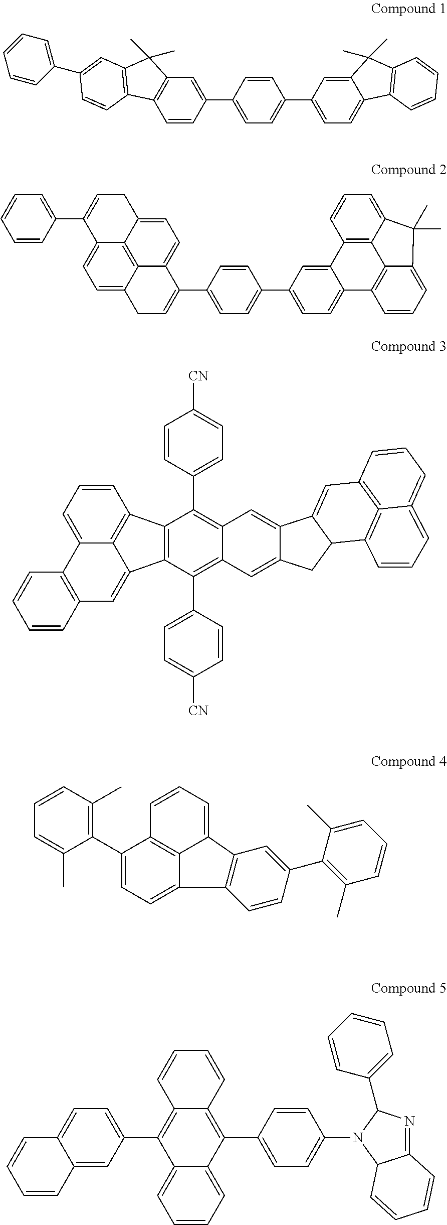
[0084]In this example (Example 1), an organic light emitting element including an anode, a hole injection layer, a hole transport layer, an emission layer, a hole blocking layer, an electron transport layer, an electron injection layer, and a cathode laminated in the stated order on a substrate was produced by a method to be described below. Part of the materials used in this example are listed below.

[0085]First, indium tin oxide (ITO) was formed into a film on a glass substrate (substrate) by a sputtering method to form the anode. At this time, the thickness of the anode was set to 110 nm. Next, the substrate on which the anode had been formed was subjected to ultrasonic cleaning with acetone and isopropyl alcohol (IPA) sequentially. Next, the cleaned product was subjected to boil cleaning with IPA, followed by drying. Further, the dried product was subjected to UV / ozone cleaning. The substrate with the anode treated as described above was used as a transparent and conduct...

Example

Comparative Example 1

[0091]An organic light emitting element was obtained by the same method as that of Example 1 except that in Example 1, a hole transport layer was formed by using Compound 6 shown below and Compound 6 was used as a host to be incorporated into an emission layer.

Example

Comparative Example 2

[0092]An organic light emitting element was obtained by the same method as that of Example 1 except that in Example 1, a hole transport layer was formed by using Compound 7 shown below and Compound 6 was used as a host to be incorporated into an emission layer.


PUM


Abstract

Provided is an organic light emitting element including: an anode; a cathode; and an organic compound layer formed between the anode and the cathode and including a hole injection layer, a hole transport layer, and an emission layer, in which: the emission layer includes a host and a dopant; the hole transport layer includes a hole transport material having multiple aromatic hydrocarbon skeletons and a single bond for linking the aromatic hydrocarbon skeletons; the hole transport material has a triplet level T1 of 1.8 eV or more; the hole transport material has a hole mobility of 1×10⁻⁵ cm2/Vs or more; and the hole transport layer and the emission layer satisfy relationships represented by the following expression (1):
|reduction potential of hole transport material|−|reduction potential of host|>0.1 V  (1)
and the following expression (2): |HOMO level of hole transport material-HOMO level of host|<0.1 eV (2).

Description

TECHNICAL FIELD[0001]The present invention relates to an organic light emitting element.BACKGROUND ART[0002]An organic light emitting element is an electronic element including an anode, a cathode, and a thin film containing a luminous organic compound, formed between the anode and the cathode. A voltage is applied between the anode and the cathode to inject a hole and an electron, whereby the organic light emitting element is driven. Specifically, the hole and electron applied from the respective electrodes recombine in the element (the thin film containing the luminous organic compound), and when the luminous organic compound in an excited state (exciton) produced by the recombination returns to its ground state, light is radiated. The organic light emitting element is an element that utilizes the light to be radiated.[0003]From the viewpoint of a light emission principle, light emissions of the organic light emitting element can be classified into two kinds, i.e., fluorescent emi...

Claims


Application Information

Patent Timeline
IPC IPC(8): H01L51/00G03G15/04G09G3/32H05B33/08C09K11/06C09K11/02H05B44/00
CPCH01L51/0058C09K2211/1011H01L51/0055H01L51/0056H01L51/006C09K11/06C09K11/025G09G3/3208H05B33/0809G03G15/04054H01L51/5088H01L51/5056H01L51/5016H01L51/5004H01L2251/552H01L2251/554H01L51/504H01L51/5024C09K2211/1007H01L51/0054H10K85/622H10K85/626H10K50/11H10K2101/40H10K50/125H10K50/13H10K50/15H10K2101/50H10K2101/30H10K85/623H10K85/624H10K85/633H10K50/12H10K50/17H10K2101/10
Inventor ISHII, RYUJIOHRUI, HIROKITAGAMI, KEIITABASHI, MASUMI
Owner CANON KK
Why Eureka
Try Eureka