
Active water phantom for three-dimensional ion beam therapy quality assurance

a three-dimensional ion beam therapy and active water technology, applied in the field of dosimetry for radiotherapy treatments for cancer, can solve problems such as bottlenecks that limit patient throughput at ion beam therapy clinics

Inactive Publication Date: 2016-05-19
BROOKHAVEN SCI ASSOCS
View PDF2 Cites 20 Cited by
  • Summary
  • Abstract
  • Description
  • Claims
  • Application Information

AI Technical Summary

Benefits of technology

The present invention provides an Active Water Phantom that can simulate an "ideal" patient and scintillate to reveal the radiation dose delivered by an ion beam. This Active Water Phantom combines the traditional use of water as a preferred passive phantom with the recent breakthrough development of a water-based liquid scintillator material. By using light generated in the scintillator, the invention eliminates the need for a separate detector. The scintillation light generated is viewed by cameras, detectors, or other sensors from three sides, providing simultaneous two-dimensional projections of the radiation dose. The system is designed to provide improved tissue equivalence, better spatial resolution, adjustable scintillation yield, and ease of handling compared to conventional liquid scintillators. The scintillation light is transported from the water tank to remote photo-detectors through hoods designed to minimize reflections of the generated light.

Problems solved by technology

In particular, present QA technology typically requires physical movement of a gas ionization chamber array during several repeated dose measurements, and is limited by time constraints to measurements for only several energy layers.
The time required for QA measurements with present technology represents a bottleneck that limits patient throughput at ion beam therapy clinics.

Method used


Image

  • Active water phantom for three-dimensional ion beam therapy quality assurance
  • Active water phantom for three-dimensional ion beam therapy quality assurance
  • Active water phantom for three-dimensional ion beam therapy quality assurance

Examples


Embodiment Construction

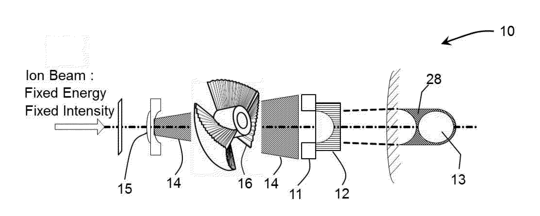
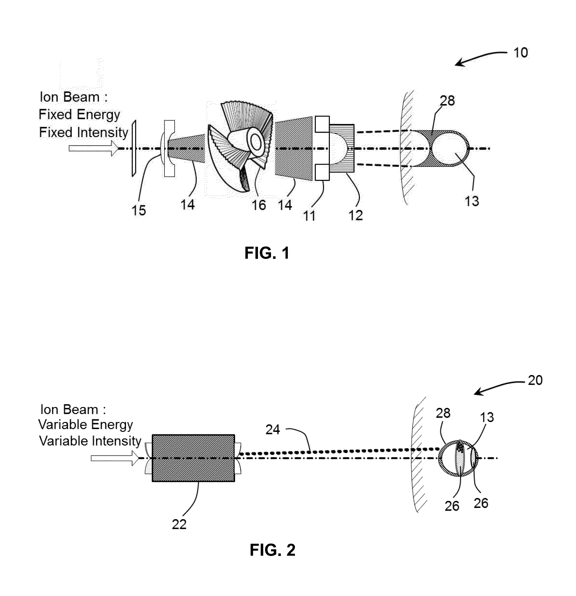
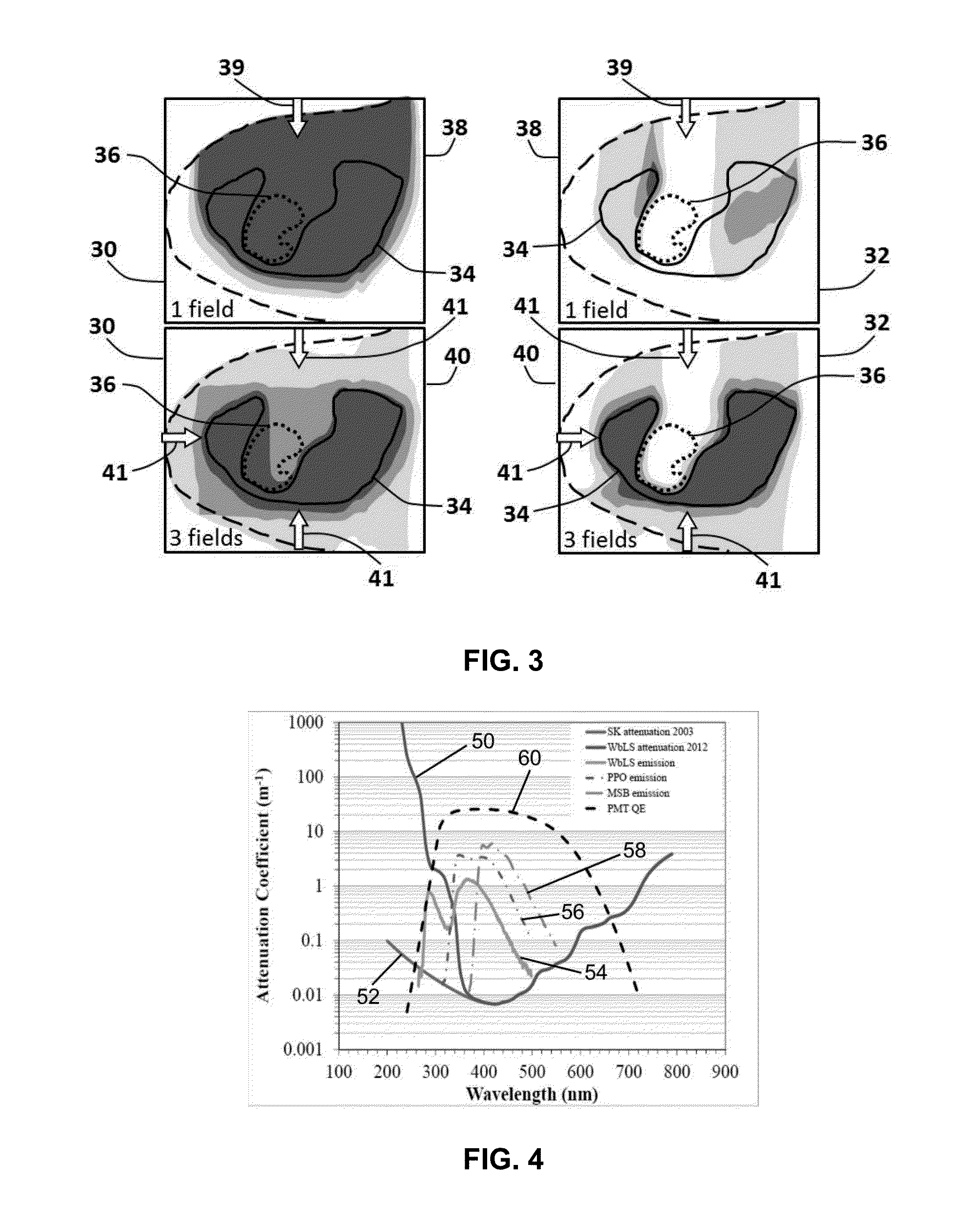
[0037]FIG. 1 shows a schematic layout of a conventional fixed-energy, fixed-intensity passive scattering system 10 for ion beam therapy delivery to a target volume, or tumor 13, using patient-specific apertures 11 and compensators 12 to form the desired radiation field from the broad beam 14 produced via scattering foils 15 and a range modulator 16. For comparison, FIG. 2 is a schematic view showing a system 20 for delivery of variable-energy, intensity-modulated ion beam therapy, using a scanning system 22 to scan a pencil beam 24 across depth layers 26 of a tumor. Two representative depth layers 26 are indicated in the figure. The shaded areas 28 in FIGS. 1 and 2, schematically indicating dose distributions outside the tumor volume, illustrate how pencil beam scanning can lead to reduced irradiation of healthy tissue adjacent to the tumor.

[0038]FIG. 3 is a schematic illustration which compares proton therapy dose delivery plans for the same two approaches shown schematically in FI...


PUM


Abstract

An Active Water Phantom is designed to provide fast, accurate, high resolution, complete Quality Assurance of patient-specific treatment plans utilizing intensity-modulated Ion Beam Therapy, prior to their delivery to the patient. The detection medium is a tissue-equivalent water-based liquid scintillator material. A three-dimensional pattern of scintillation light, emitted upon ion beam irradiation, is reconstructed from three orthogonal two-dimensional light yield profiles, which are read out for each individual beam energy layer. The 3-D information has dose measurement accuracy 1-2% and spatial resolution 1-2 millimeters. The measurement sequence provides up to four orders of magnitude more data characterizing the treatment plan than currently commercially available alternatives, all in a time period no greater than that needed for actual delivery of the dose fraction to a patient. The system provides sophisticated control and readout of the cameras or photo-detectors, data archiving and analysis, simulation capabilities, and 3-D dose image reconstruction and visualization.

Description

STATEMENT OF GOVERNMENT RIGHTS[0001]This invention was made with Government support under contract number DE-AC02-98CH10886, awarded by the U.S. Department of Energy. The Government has certain rights in the invention.FIELD OF THE INVENTION[0002]The present invention is in the technical field of dosimetry for radiotherapy treatments for cancer. More particularly, the present invention is in the technical field of dosimetry for quality assurance of ion beam therapy treatment plans, based on the scanning of intense accelerator beams of small cross-sectional area (so-called “pencil” beams), and of adjustable energy and intensity, to irradiate the full volume of an arbitrary-shaped target tumor conformally, while providing minimal dose to surrounding healthy tissue.BACKGROUND OF THE INVENTION[0003]In comparison to standard X-ray therapy, proton or heavier-ion beam therapy is capable of significantly improving dose localization by increasing dose delivered to the target volume while mini...

Claims


Application Information

Patent Timeline
IPC IPC(8): A61B6/00G01T1/20
CPCA61B6/4258G01T1/20A61B6/583G01T1/169A61N5/1075A61N2005/1076A61N2005/1087
Inventor VIGDOR, STEVEN E.YEH, MINFANGJAFFE, DAVID E.
Owner BROOKHAVEN SCI ASSOCS
Learn More