Electroactive actuators

a technology of actuators and actuators, applied in the field of actuators, can solve the problems of iabps not being able to deploy for long periods of time, restricting patients to bed rest, and requiring percutaneous tubes

Active Publication Date: 2016-05-26
NOTTINGHAM TRENT UNIVERSITY +1
View PDF3 Cites 39 Cited by
  • Summary
  • Abstract
  • Description
  • Claims
  • Application Information

AI Technical Summary

Benefits of technology

[0033]v) relaxing the layer of dielectric e...

Problems solved by technology

However, this restricts the patient to bed rest, and prolonged implantation can be associated with infections in the groin crease and generalised sepsis from contamination of the balloon catheter from microorganisms present at the insertion site.
IABPs cannot be deployed for long periods of time because of the risks of sepsis, arterial wall trauma, ischaemia in the relevant limb distal to the insertions site, thrombolic complications from exposure of the blood to a large surface area of foreign material, clotting abnormalities secondary to platelet consumption and device failure since their thin silicone balloons are prone to rupture.
This allows for greater freedom of mobility for the patient, but the problem remains that a percutaneous tube is required (Legget et al, 2005).
This is partly due to the restricted space available for installation around the ascending aorta.
At a time when such a device might be implanted, the aorta itself will tend to be diseased, becoming hardened through atherosclerosis and likely suffering from a narrowing of bore (stenosis).
Other disadvantages of EABPs can include increasing atheromous emboli (accumulation of plaque inside the aorta) through interaction with the aortic wall and migration an...

Method used


Image

  • Electroactive actuators
  • Electroactive actuators
  • Electroactive actuators

Examples


Embodiment Construction

[0042]The invention is described in further detail below by way of example and with reference to the accompanying drawings, in which:

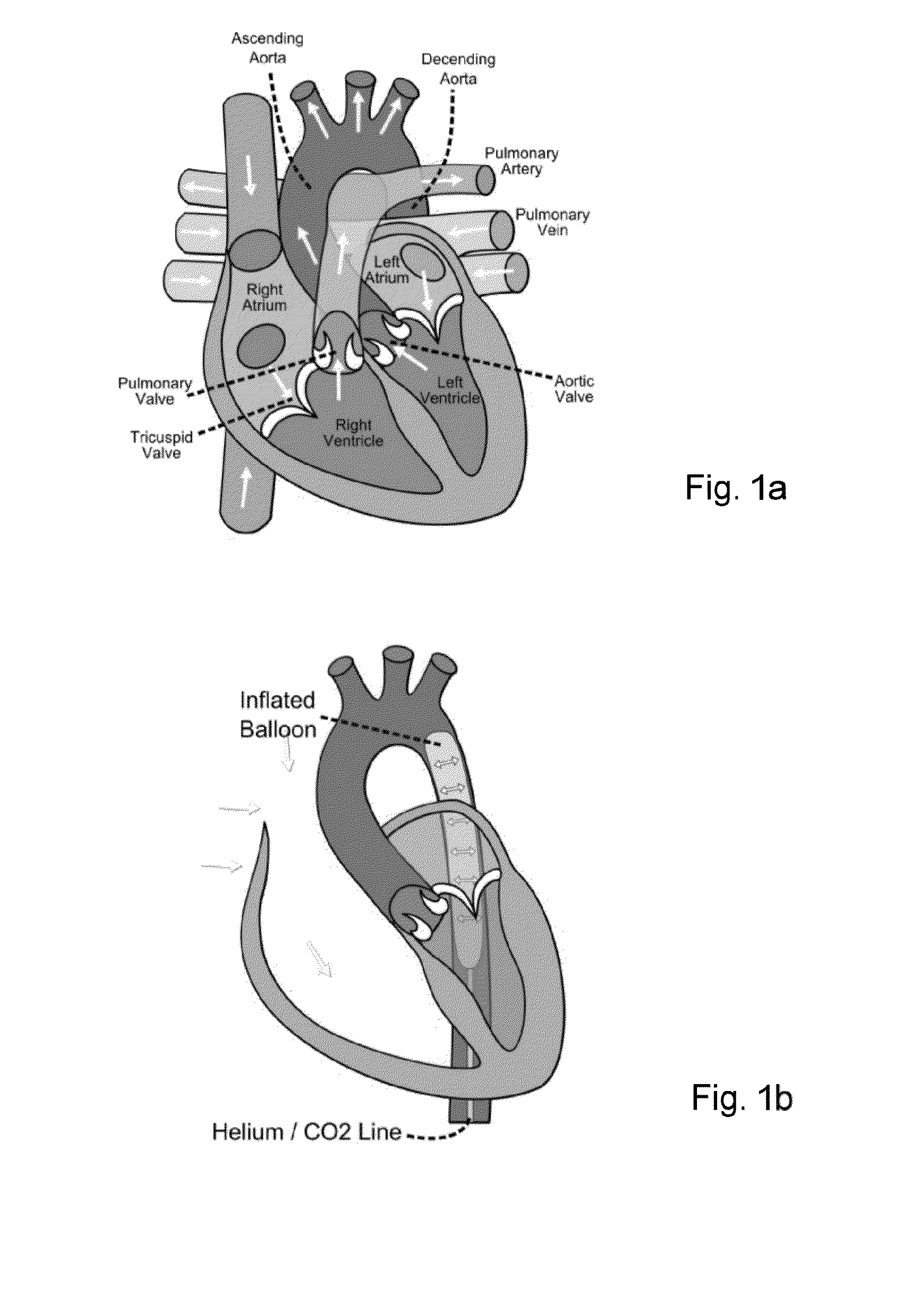
[0043]FIG. 1a is a schematic cutaway diagram illustrating the main components of a human heart;

[0044]FIG. 1b is a schematic illustration of an intra-aortic balloon pump in place within an aorta;

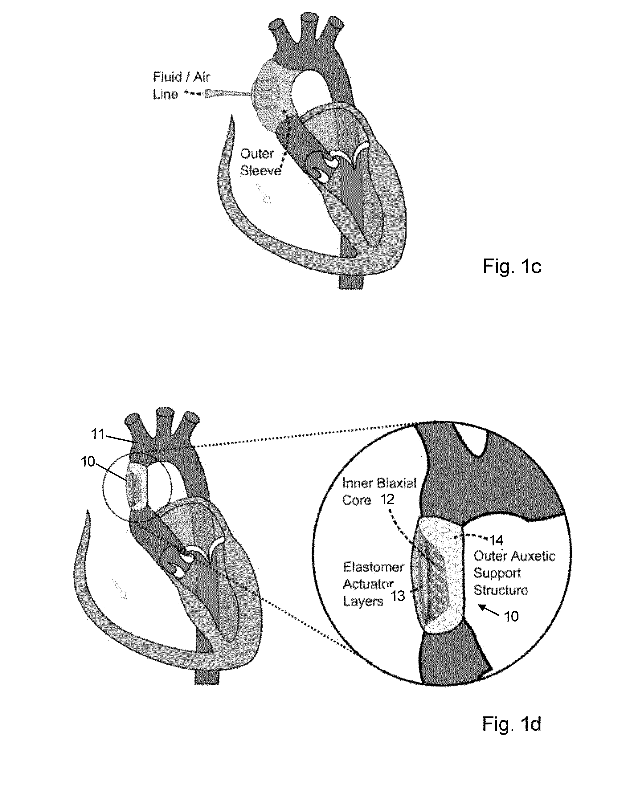
[0045]FIG. 1c is a schematic illustration of an extra-aortic balloon pump in place around an aorta;

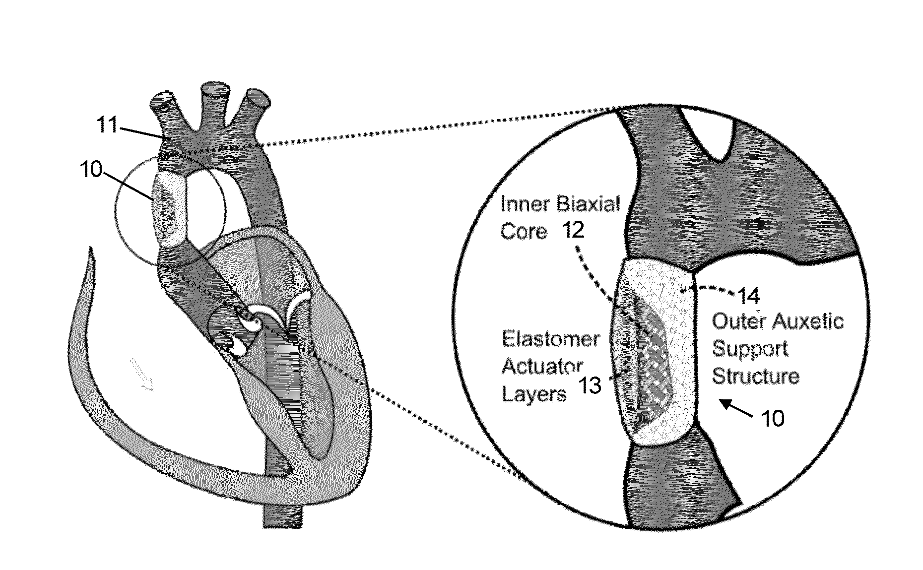
[0046]FIG. 1d is a schematic drawing of an exemplary actuator connected to an aorta;

[0047]FIG. 2a is a schematic cross section of the structure of an exemplary actuator;

[0048]FIG. 2b is a schematic diagram illustrating the arrangements of interleaving electrodes for the exemplary actuator of FIG. 2a;

[0049]FIG. 3 is a series of schematic illustrations showing an exemplary process for fabricating the elastomeric and support structure layers of an actuator;

[0050]FIGS. 4a and 4b are photographs of exemplary braided tubular structures for an inner support structure of ...


PUM

PropertyMeasurementUnit
Dielectric polarization enthalpyaaaaaaaaaa
Ratioaaaaaaaaaa
Electric potential / voltageaaaaaaaaaa

Abstract

The invention relates to actuators based on electroactive polymeric materials for use in pumping fluids or in other applications where a contractile actuation is required, in particular although not necessarily exclusively for use in vascular pulsation devices such as a variable aortic tension device. Embodiments disclosed include an actuator (10) comprising: an inner tubular structure (15, 12); an outer tubular structure (13, 14) surrounding the inner tubular structure (15, 12) and comprising a plurality of layers of a dielectric elastomeric material (13) and a tubular elastic support structure (14), the elastic support structure (14) configured to maintain a pre-stress in the layers of the dielectric elastomeric material (13), wherein the outer tubular structure (13, 14) is configured to contract in a radial direction around the inner tubular structure (12, 15) upon application of an actuation voltage signal across the dielectric elastomeric material layers (13).

Description

FIELD OF THE INVENTION[0001]The invention relates to actuators based on electroactive polymeric materials for use in pumping fluids or in other applications where a contractile actuation is required, in particular although not necessarily exclusively for use in vascular pulsation devices such as a variable aortic tension device.BACKGROUND[0002]The current state of the art of implantable cardiac assist technology consists of either a cannula-coupled constant flow pump which heavily supplements the left ventricle, or an implantable intra-aortic balloon.[0003]Intra-Aortic Balloon Pumps (IABPs) such as those described in U.S. Pat. No. 6,210,318 and EP 0192574 (also published as U.S. Pat. No. 4,697,574) are well established technology which comprise of a mechanical device that sits at the top of the descending aorta. The device counterpulsates synchronously but in anti-phase with the heartbeat. This has the effect of increasing coronary blood flow and reducing afterload (known as aortic ...

Claims


Application Information

Patent Timeline
IPC IPC(8): A61M1/10B29C67/00A61M1/12A61M60/139A61M60/161A61M60/289A61M60/295A61M60/486A61M60/497A61M60/562
CPCA61M1/122A61M1/107B29C67/0055A61M2205/0283A61M2207/00A61M1/1046B33Y80/00B29K2083/00B29L2009/005B29L2031/7534B33Y10/00A61F2/0036A61F2250/0001B29C64/118A61M60/00A61M60/562A61M60/268A61M60/40A61M60/274A61M60/50A61M60/148H10N30/886H10N30/506H10N30/05A61M60/139A61M60/161A61M60/486A61M60/289A61M60/295A61M60/497
Inventor BREEDON, PHILIPCOULTER, FERGALRICHENS, DAVID
Owner NOTTINGHAM TRENT UNIVERSITY
Why Eureka
Try Eureka