
Phosphor-Dispersed Glass and Method for Producing Same

a technology of phosphor-dispersed glass and phosphor-dispersed glass, which is applied in the direction of red component light (wavelength: 600 nm) that is not sufficient, and can solve the problems of inhibiting the operation of led elements, degradation of resins, and insufficient cyan component light (wavelength: up to 500 nm) to achieve the effect of suppressing the deactivation of phosphor

Inactive Publication Date: 2016-06-02
CENT GLASS CO LTD
View PDF6 Cites 5 Cited by
  • Summary
  • Abstract
  • Description
  • Claims
  • Application Information

AI Technical Summary

Benefits of technology

This patent proposes a method to improve the lifespan and color-rendering properties of LED devices. By mixing phosphor particles into glass, instead of resin, the device's lifetime can be extended. Additionally, the use of a red phosphor with high efficiency is possible, as deactivation of the nitride phosphor is suppressed. This results in a high-color-rendering LED device.

Problems solved by technology

However, the conventional combination of YAG-Ce phosphors and blue LED elements faces the problem that cyan component light (wavelength: up to 500 nm) and red component light (wavelength: 600 nm) are not sufficient.
There are however problems such as degradation of the resin by an ultraviolet light from phosphor excitation light source, inhibition of operation of the LED element by penetration of water in the resin during long-term use etc.
In this case, however, there is a possibility that the phosphor precipitates due to a difference in specific gravity between the phosphor and the glass melt.

Method used


Image

  • Phosphor-Dispersed Glass and Method for Producing Same

Examples


example 1

[0066]Fluoride glass materials were obtained by using and mixing raw fluoride compounds at respective mol % as shown in Nos. 1 to 9 of TABLE 1, placing the raw glass compound mixture in a crucible of glassy carbon, melting the raw glass compound mixture at 980° C. for 1 hour in an atmosphere of 99% nitrogen and 1% chloride as a partial pressure component, and then, rapidly cooling the glass melt.

[0067]The softening temperature (Ts) of the respective fluoride glass materials was measured. The measurement of the softening temperature (Ts) was done with the use of a wide-range viscometer (WRVM-313 available from OPT Corporation). Each of the obtained fluoride glass materials had a softening temperature (Ts) of 500° C. or lower.

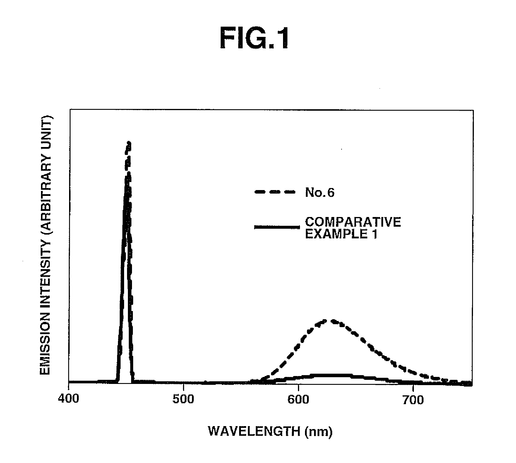
[0068]Subsequently, each of the obtained fluoride glass materials was pulverized into a powder of glass particles with a median diameter d50 of 10 μm, following by adding thereto 5 mass % of particles of nitrogen phosphor (CaAlSiN3:Eu2+, luminescence center wavel...

example 2

[0081]A sample was formed in the same manner as in Example 1 by using the same fluoride glass material as the sample No. 6 of TABLE 1 and using YAG-Ce phosphor in place of the nitride phosphor.

[0082]The internal quantum efficiency of the YAG-Ce phosphor before encapsulation in the glass material was measured to be 83%. By contrast, the internal quantum efficiencies of the glass sample of Example 2 was 74%. It has been shown by these results that: it is possible for the fluoride glass material of the present invention to suppress deactivation of the phosphor; and the fluoride glass material of the present invention is usable for encapsulation of an oxide phosphor.


PUM

PropertyMeasurementUnit
Temperatureaaaaaaaaaa
Fractionaaaaaaaaaa

Abstract

A phosphor-dispersed glass according to one aspect of the present invention includes phosphor particles and a phosphor encapsulant, wherein the phosphor encapsulant is a fluoride glass material containing 1 to 45 mol % of AlF3, 30 to 60 mol % of a sum of a fluoride of Hf and a fluoride of Zr, 20 to 65 mol % of alkaline earth fluorides in total, 2 to 25 mol % in total of at least one fluoride of element selected from the group consisting of Y, La, Gd and Lu and 0 to 20 mol % in total of at least one fluoride of element selected from the group consisting of Na, Li and K. It is feasible in this phosphor-dispersed glass to suppress deactivation of the phosphor particles regardless of the kind of the phosphor.

Description

FIELD OF THE INVENTION[0001]The present invention relates to a fluoride glass material capable of encapsulating therein a luminescent substance without causing deactivation of the luminescent substance.BACKGROUND ART[0002]White LED devices have recently been put into use as illumination light sources in place of filament lamps. Many of currently available white LED devices realize pseudo white light by combination of YAG-Ce yellow oxide phosphors and GaN blue LED elements.[0003]However, the conventional combination of YAG-Ce phosphors and blue LED elements faces the problem that cyan component light (wavelength: up to 500 nm) and red component light (wavelength: 600 nm) are not sufficient. It is thus common practice to supplement these insufficient component lights by mixing a plurality of phosphors. For example, Patent Document 1 discloses a high-color-rendering white light source using a YAG-Ce phosphor in combination of a red-emitting Eu complex.[0004]Further, nitride phosphors h...

Claims


Application Information

Patent Timeline
IPC IPC(8): C03C14/00C03C3/32C09K11/77
CPCC03C14/006C03C3/325C09K11/7706C09K11/7734C03C2214/30H01L33/501C09K11/77348
Inventor OKAMOTO, HIDEYUKIKASUGA, KENSEKI, KOHEIOMI, SHIN
Owner CENT GLASS CO LTD
Learn More