
Method for purification of off-gas and device for the same

a technology of purification method and purification device, which is applied in the direction of physical/chemical process catalyst, metal/metal-oxide/metal-hydroxide catalyst, separation process, etc., can solve the problems of high maintenance cost, low energy efficiency, and complex process, and achieve simple and low energy device, elution of impurities in activated carbon, and high purity

Inactive Publication Date: 2016-06-16
HANWHA CHEMICAL CORPORATION
View PDF3 Cites 3 Cited by
  • Summary
  • Abstract
  • Description
  • Claims
  • Application Information

AI Technical Summary

Benefits of technology

The present invention provides a method and device for purifying off-gas by removing hydrogen chloride from it. This helps to decrease problems caused by hydrogen chloride, such as corrosion and leakage of chlorosilane, and prepares high-purity hydrogen. The method is simple and low-energy, reducing facility and process operation costs.

Problems solved by technology

The pressure swing adsorption process has disadvantages in that energy efficiency is low because it consists of condensing and compression process, and maintenance cost is high because it is a physical process.
However, the existing pressure swing adsorption device has disadvantages in that the adsorption process and the regeneration process are separately progressed, and thus, the process is very complicated, and facilities and process cost are very high.
Thus, problems such as mechanical error of the apparatus, shortening of life, and leakage of chlorosilane compounds, and the like may be caused due to the corrosion by hydrogen chloride, and the purity of polysilicon may be influenced.

Method used


Image

  • Method for purification of off-gas and device for the same
  • Method for purification of off-gas and device for the same
  • Method for purification of off-gas and device for the same

Examples


experimental example

Evaluation of the Performance of a Catalytic Reactor by Reaction Simulation

experimental example 1

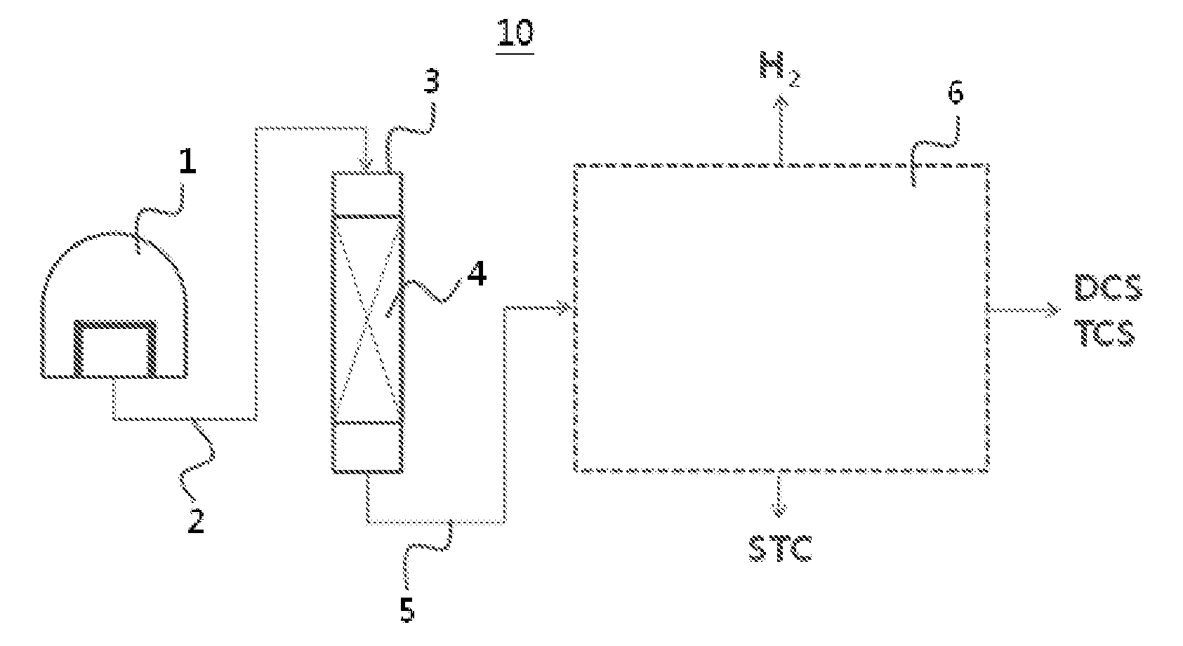
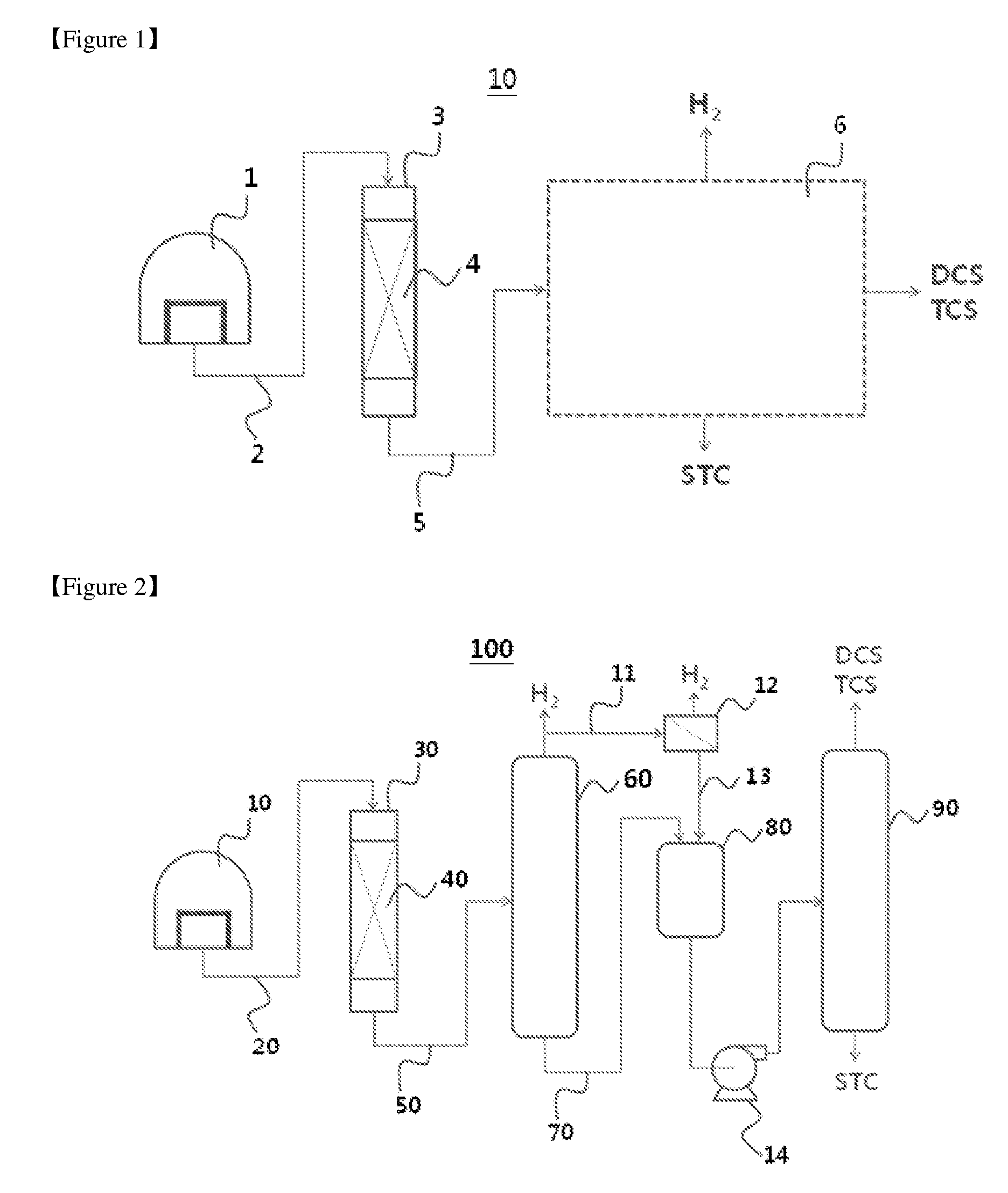
[0093]Off-gas was purified using the purification device shown in FIG. 1. In order to confirm the performance, the process was simulated using a process simulation program ASPEN Plus.

[0094]The reaction temperature and the pressure of the catalytic reactor 3 were set at 170° C. and 5 barG, and the composition of the stream introduced in the catalytic reactor 3 was set to consist of 1 mol % of hydrogen chloride, 2 mol % of dichlorosilane, 10 mol % of trichlorosilane, 7 mol % of silicon tetrachloride, and 80 mol % of hydrogen. As the catalytic reactor 3, R-Gibbs and R-Stoic models were used.

[0095]As the result of simulation under the above conditions, the mixed gas 5 that has passed through the catalytic reactor 3 consisted of 1 mol % of dichlorosilane, 12 mol % of trichlorosilane, 7 mol % of silicon tetrachloride, and 80 mol % of hydrogen, and it was confirmed that hydrogen chloride reacts with dichlorosilane under the given reaction conditions and is removed, and is converted into hi...

experimental example 2

[0096]Off-gas was purified using the purification device shown in FIG. 2. In order to confirm the performance, the process was simulated using a process simulation program ASPEN Plus.

[0097]The reaction temperature and the pressure of the catalytic reactor 30 were set at 170° C. and 5 barG, and the composition of the stream introduced in the catalytic reactor 30 was set to consist of 1 mol % of hydrogen chloride, 2 mol % of dichlorosilane, 10 mol % of trichlorosilane, 7 mol % of silicon tetrachloride, and 80 mol % of hydrogen. As the catalytic reactor 30 was R-Gibbs and R-Stoic models were used.

[0098]The purification temperature in the primary distillation column 60 was set at −5˜−60° C., and the pressure was set at 23 barG. It was set that the composition of the mixed gas 50 stream introduced in the primary distillation column 60 was identical to the composition obtained as the simulation result for the catalytic reactor 30, which consisted of 1 mol % of dichlorosilane, 12 mole % of...


PUM

PropertyMeasurementUnit
temperatureaaaaaaaaaa
boiling pointaaaaaaaaaa
temperatureaaaaaaaaaa

Abstract

This disclosure relates to a method for purification of off-gas and a device for the same. More particularly, this disclosure relates to a method for purification of off-gas that removes hydrogen chloride from the off-gas discharged after conducting a polysilicon deposition process by chemical vapor deposition, and can separate hydrogen of high purity, and a device for the same.

Description

TECHNICAL FIELD[0001]This disclosure relates to a method for purification of off-gas and a device for the same. More particularly, this disclosure relates to a method for purification of off-gas that removes hydrogen chloride from the off-gas discharged after conducting a polysilicon deposition process by chemical vapor deposition, and can separate hydrogen of high purity, and a device for the same.[0002]This application claims the benefit of Korean Patent Application No. 10-2013-0102573 filed on Aug. 28, 2013 in the Korean Intellectual Property Office, the entire disclosure of which is herein incorporated by reference.BACKGROUND ART[0003]One of the methods known to produce polysilicon for a solar cell is by deposition of polysilicon in a chemical vapor deposition (CVD) reactor, which is known as a Siemens process.[0004]In the Siemens process, silicon filaments are commonly exposed to trichlorosilane together with carrier gas at high temperature of 1000° C. or more. The trichlorosil...

Claims


Application Information

Patent Timeline
Patent Type & Authority Applications(United States)
IPC IPC(8): B01D53/86
CPCB01D53/8659B01D2258/0216B01D2255/1021B01D2255/207B01D2257/2045B01D53/68B01J23/40B01J23/755B01D2253/102B01D2255/102B01D2255/20753B01D2256/16B01D2256/26B01J21/18B01J23/42B01D53/86B01D53/74
Inventor KIM, GIL HOLEE, WON IKAHN, GUI RYONGKIM, BO KYUNG
Owner HANWHA CHEMICAL CORPORATION
Learn More