Polyolefin microporous membrane and separator for nonaqueous electrolyte battery

a technology of polyolefin microporous membrane and electrolyte battery, which is applied in the direction of batteries, cell components, cell component details, etc., can solve the problems of inability to reach short-circuit, insufficient satisfaction, and uneven pressure distribution of batteries, and achieve excellent permeability and mechanical strength, and pores fine

Active Publication Date: 2016-06-23
ASAHI KASEI CHEM CORP
View PDF1 Cites 16 Cited by
  • Summary
  • Abstract
  • Description
  • Claims
  • Application Information

AI Technical Summary

Benefits of technology

[0020]The present invention provides a microporous membrane having fine pores and excellent in permeability and mechanical strength in an initial stage and creep. In particular, the present invention can provide a microporous membrane particularly preferable as a separator for a nonaqueous electrolyte battery etc. which are required to be excellent in safety and long-term reliability.

Problems solved by technology

Further, when a foreign object such as a fallen active material exists, the electrodes generate swelling and shrinkage by repeating charge and discharge of a battery, and there is a possibility that the foreign object is pushed to the separator for long period of time to thereby penetrate the separator and reach short-circuit.
Further, along with having a high energy density and high output, a rolled-up structure and a collector structure are diversified and pressure distribution in a battery is not uniform, and a high pressure may be continuously applied locally on a separator in some cases, and in such cases, there is a possibility to reach short-circuit.
In order to solve these problems of safety and long-term reliability, various studies have been made, but these have not been necessarily satisfactory.
Further, since boundary separation is performed by stretching in preference to extension of ramera and rearrangement in the production method, there is a limitation on high puncture strength.
Furthermore, since there is a possibility to accidentally generate a void with a large porous diameter in the boundary separation, when using as a separator of a lithium ion battery etc., there is a concern on reliability such as slight short-circuit and self discharge.
However, a draw ratio is as low as about 6 times, and high puncture strength can not be achieved.
Further, in the case of stretching by a large ratio, a porous structure is coarsened with a starting point of an agglomerate, and further, membrane rupture is likely to be caused.
However, a porous film disclosed in Examples has a draw ratio is as small as 2×2 times, and thus high puncture strength can not be achieved.
However, since the substrate is a flexible nonwoven fabric, or the like, there is a limitation on high puncture strength and compression resistance characteristics.

Method used

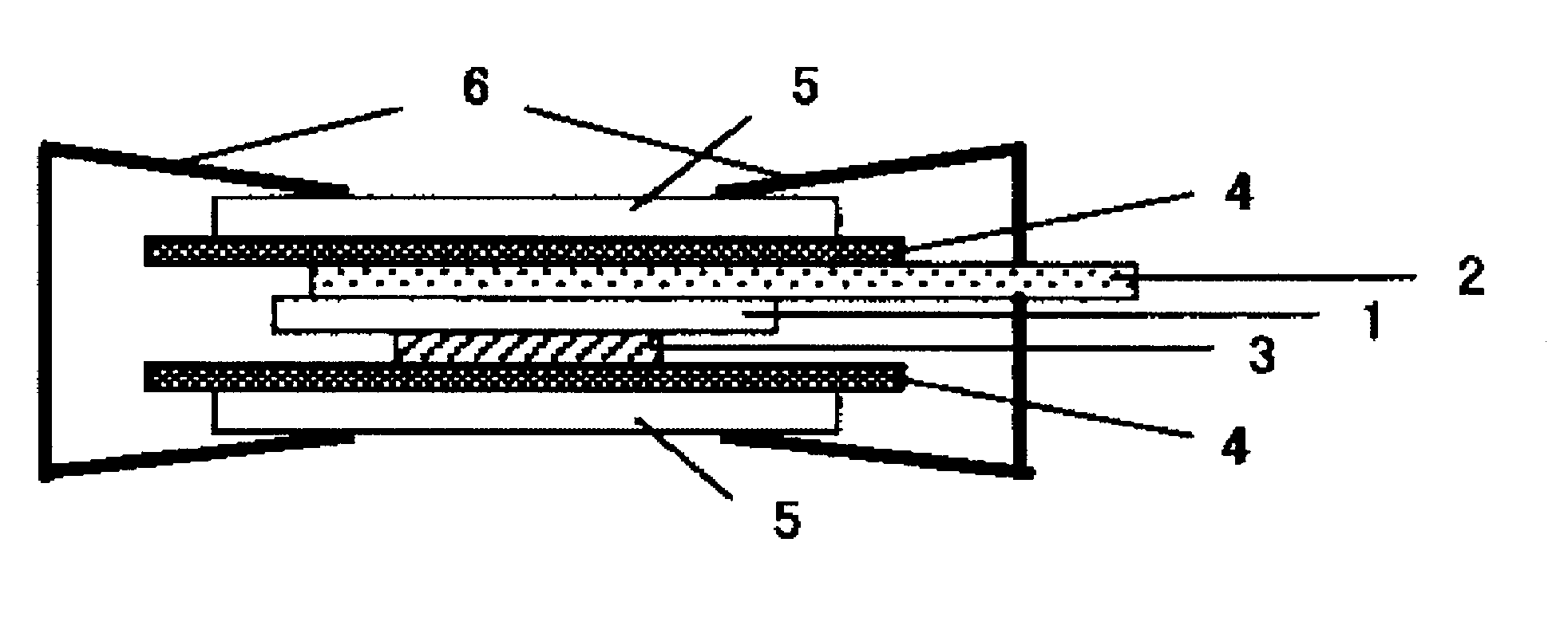
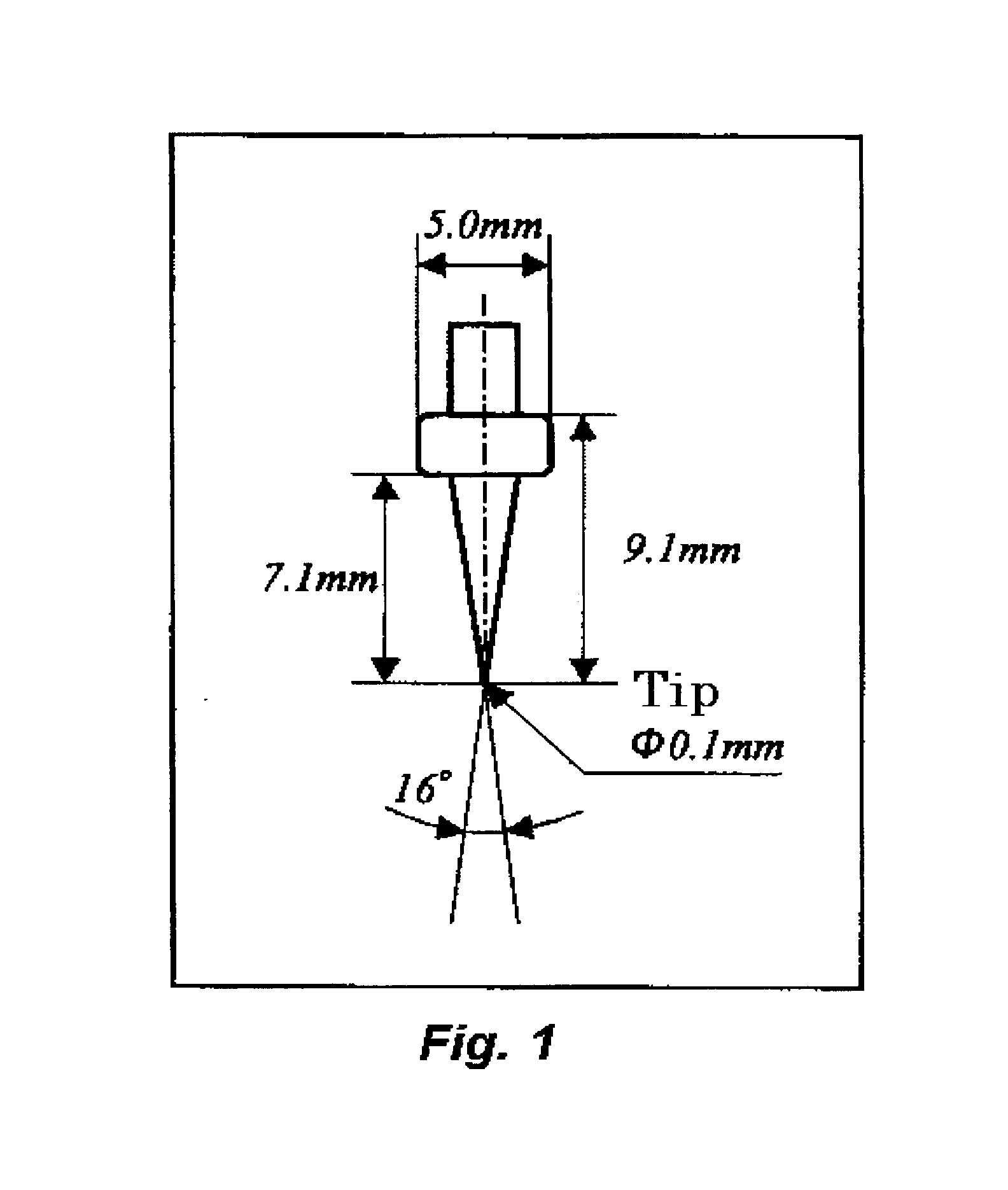
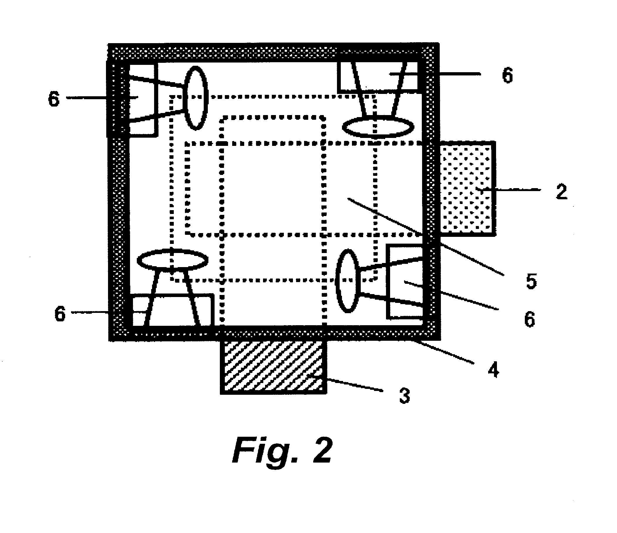

Image

  • Polyolefin microporous membrane and separator for nonaqueous electrolyte battery
  • Polyolefin microporous membrane and separator for nonaqueous electrolyte battery
  • Polyolefin microporous membrane and separator for nonaqueous electrolyte battery

Examples


example 1

[0100]18 parts by mass of high density polyethylene “SH800” (trademark, made by Asahi Kasei Chemicals Corporation) having a viscosity average molecular weight (Mv) of 270,000, 12 parts by mass of an ultra-high molecular weight polyethylene “UH850” (trademark, made by Asahi Kasei Chemicals Corporation) having Mv of 2,000,000, 20 parts by mass of silica “DM10C” (trademark, made by TOKUYAMA Corporation, hydrophobic treatment was carried out with dimethyldichlorosilane) having an average primary particle diameter of 15 nm, 30 parts by mass of a liquid paraffin “SMOIL P-350P” (trademark, made by Matsumura Oil Research Corp.) as a plasticizer, and 0.3 part by mass of pentaerythrityl-tetrakis-[3-(3,5-di-t-butyl-4-hydroxyphenyl)propionate] as an antioxidant were added and preliminarily mixed by a super mixer. The resultant mixture was fed into a feeding inlet of a twin screw extruder in which two screws rotate in the same direction by a feeder. Further, the liquid paraffin was side-fed into...

example 2

[0101]A microporous membrane was obtained in the same manner as in Example 1 except for using 9 parts by mass of the high density polyethylene having Mv of 270,000, 13.5 parts by mass of the ultra-high molecular weight polyethylene having Mv of 2,000,000, 27.5 parts by mass of the silica “DM10C” (trademark, made by TOKUYAMA Corporation, hydrophobic treatment was carried out with dimethyldichlorosilane) having an average primary particle diameter of 15 nm, and 40 parts by mass of the liquid paraffin in Example 1 and preliminarily mixing by a super mixer. Membrane preparation conditions and membrane characteristics are shown in Table 1.

example 3

[0102]A microporous membrane was obtained in the same manner as in Example 1 except for using 24 parts by mass of the high density polyethylene having Mv of 270,000, 16 parts by mass of the ultra-high molecular weight polyethylene having Mv of 2,000,000, 10 parts by mass of the silica “DM10C” (trademark, made by TOKUYAMA Corporation, hydrophobic treatment was carried out with dimethyldichlorosilane) having an average primary particle diameter of 15 nm, and 20 parts by mass of the liquid paraffin and preliminarily mixing by a super mixer, and changing a setting temperature of lateral stretching to 125° C. and a setting temperature in an relaxing part to 130° C. Membrane preparation conditions and membrane characteristics are shown in Table 1.


PUM

PropertyMeasurementUnit
particle diameteraaaaaaaaaa

Abstract

The present invention provides a polyolefin microporous membrane made of a polyolefin resin and an inorganic particle, and the puncture strength of the microporous membrane is 3 N / 20 μm or more and the membrane thickness retention ratio in penetration creep is 16% or more, thereby being excellent in safety and long-term reliability, and a separator for a nonaqueous electrolyte battery, and the like can be provided.

Description

TECHNICAL FIELD[0001]The present invention relates to a microporous membrane suitable for a filtration membrane, a moisturizing membrane, and the like, which require permeability and mechanical strength in an initial stage and creep, and a microporous membrane suitable as a separator for a nonaqueous electrolyte battery excellent in safety and reliability. Further, the present invention relates to a lithium ion secondary battery using the microporous membrane as a separator.BACKGROUND ART[0002]A microporous membrane has various porous diameters, porous shaped, and the porous numbers, and has been utilized in wide variety of fields due to characteristics capable of exhibiting by its specific structure. For example, a microporous membrane is used as, for example, a separating membrane used for a water treatment, concentration, etc, utilizing a sieve effect due to difference in a porous diameter, an adsorption sheet used in materials for water absorption, oil absorption, and deodorant,...

Claims


Application Information

Patent Timeline
Patent Type & Authority Applications(United States)
IPC IPC(8): H01M2/16H01M10/0525H01M50/417H01M50/434H01M50/489
CPCH01M2/1633H01M2220/20H01M10/0525B01D71/26C08J5/18C08J2323/00Y02E60/10H01M50/446H01M50/417H01M50/434H01M50/489C08J9/35C08J9/22H01M50/431Y02T10/70B01D71/261B01D71/262
Inventor HATAYAMA, HIROSHISOGO, HIROSHI
Owner ASAHI KASEI CHEM CORP
Why Eureka
Try Eureka