Optical film

a technology of optical film and film film, applied in the field of optical film, can solve the problem that the desired effect cannot be easily guaranteed, and achieve the effect of improving light utilization efficiency

Active Publication Date: 2016-06-30
LG CHEM LTD
View PDF4 Cites 22 Cited by
  • Summary
  • Abstract
  • Description
  • Claims
  • Application Information

AI Technical Summary

Benefits of technology

[0084]In the embodiment of the present application, control of the alignment state of the liquid crystal compound in the liquid crystal layer can allow the liquid crystal layer to exhibit the so-called reverse-wavelength dispersion even while forming a thin single layer. The optical film including the above-described liquid crystal layer may exhibit optical modulation in the display device such as the LCD, OLED, or the like, or may be used for various purposes such as an optical element capable of improving light utilization efficiency or an element for an implementation of stereoscopic images and quality improvement thereof.

Problems solved by technology

Referring to FIG. 2, when the graph is linear (201, FIG. 2), that is, when a rotation angle of the liquid crystal compound constantly changes, a desired effect may not be easily ensured.
For example, these include an error in which a manufacturing error, a variation, or the like is considered.

Method used


Image

  • Optical film
  • Optical film
  • Optical film

Examples


preparation example

Preparation of Liquid Crystal Compositions

[0101]Liquid crystal compositions were prepared by the following method. RM1230 (compositions including a chiral dopant) and RM1231 (compositions not including a chiral dopant), which are reactive mesogens (RMs) available from Merck & Co., Inc. that are well known for use in preparation of a cholesteric liquid crystal (CLC) were mixed in a ratio of 1:1, and then mixed with a mixing solvent of toluene and cyclohexanone (mixing weight ratio=7:3 (toluene:cyclohexanone)) to form about 40 wt % of solid fractions. Subsequently, a photo-polymerization initiator (Irgacure 907) having a maximum absorption wavelength in a range of 280 to 320 nm as a radical initiator was mixed at 3 wt % with respect to the solid fractions of RMs, and a photo-polymerization initiator (Darocure TPO) having a maximum absorption wavelength in a range of 360 to 400 nm was also mixed at 0.4 wt % with respect to the solid fractions of RMs. Thereafter, the mixed solution was ...

example 1

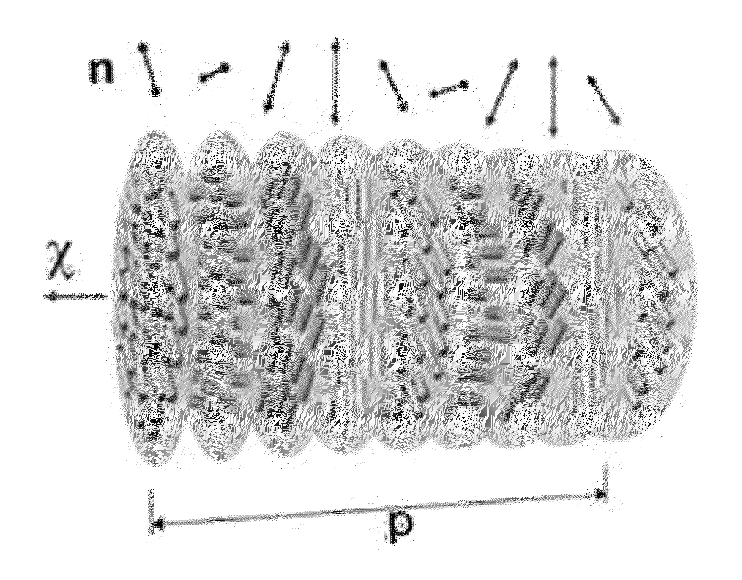
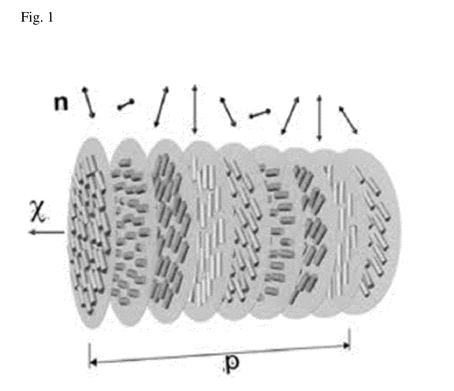
[0102]After a well-known rubbing alignment layer was formed on one surface of a poly(ethylene terephthalate) (PET) film, the alignment layer was coated with the prepared compositions using a wire bar No. 6, and then dried at 100° C. for about two minutes. Then, a concentration gradient of a chiral agent was induced by irradiating the coating layer with ultraviolet rays having a wavelength in a range of 350 to 400 nm using an ultraviolet irradiation device (TLK40W / 10R; available from Royal Philips Electronics N.V.) at a temperature of about 60° C. (intensity of irradiation: about 100 mJ / cm2). Thereafter, the coating layer on which the concentration gradient was induced was irradiated with the strong ultraviolet rays at an intensity of 1 mJ / cm2 or more using the ultraviolet irradiation device (Fusion UV, 400 W) to sufficiently polymerize RMs to form a TN layer having a thickness of about 3 μm. In the result of the determination using an optical polarizing microscope (available from Le...


PUM


Abstract

The present application relates to an optical film and a use thereof. In the present application, through control of an alignment state of a liquid crystal compound in a liquid crystal layer, the liquid crystal layer may exhibit so-called reverse-wavelength dispersion while forming a single thin layer. An optical film including the liquid crystal layer may show optical modulation in a display device such as a liquid crystal display (LCD), organic light emitting device (OLED), or the like, or may be used in various applications, for example, as an optical element capable of improving light utilization efficiency, an element for implementation of a stereoscopic image and quality improvement thereof, and so forth.

Description

FIELD[0001]The present application relates to an optical film, an optical laminate, and a display device.BACKGROUND[0002]Films which exhibit optical anisotropy are used for various purposes.[0003]These films may be used for purposes such as, for example, adjusting optical properties of a liquid crystal display (LCD), improving light utilization efficiency, or ensuring anti-reflectivity and visibility in an organic light emitting device (OLED). Further, the films as described above may be used to generate a stereoscopic image, or to improve quality of the stereoscopic image.PRIOR ART DOCUMENT[0004]Patent Document 1: Japanese Patent Publication No.: 1996-321381DescriptionObject[0005]The present application is directed to providing an optical film, an optical laminate and a display device. In the present application, one primary objective is to provide an optical film having so-called reverse-wavelength dispersion while being a single layer, due to an arrangement form of a liquid cryst...

Claims


Application Information

Patent Timeline
Patent Type & Authority Applications(United States)
IPC IPC(8): G02B5/30
CPCG02B5/3091G02B5/3016G02B5/3083G02F1/13363G02F1/133636G02F1/133703G02F1/1396G02F1/1397G02F2413/15G02F1/133633
Inventor LEE, DAE HEECHANG, JUN WONKIM, YOUNG JINPARK, MOON SOOBELYAEV, SERGEY
Owner LG CHEM LTD
Why Eureka
Try Eureka