Combined cycle gas turbine plant comprising a waste heat steam generator and fuel preheating step

Active Publication Date: 2016-08-11
SIEMENS ENERGY GLOBAL GMBH & CO KG
View PDF7 Cites 1 Cited by
  • Summary
  • Abstract
  • Description
  • Claims
  • Application Information

AI Technical Summary

Benefits of technology

[0014]In the event that no fuel preheating is required, e.g. in oil operation, it is by contrast possible, by means of a corresponding setting of the feed water mass flow, to operate the evaporator of the intermediate-pressure stage with a minimum superheating at the evaporator outlet of for example 10-15 K, such that no additional water accumulates in the water-steam separator, which water would then, if necessary, have to be discharged as waste water. In the case of intermediate-pressure stages having an additionally integrated recirculation pump in the branching-off line of the water-steam separator, it is by contrast possible, in oil operation, also with oversupplied intermediate-pressure evaporator, for the resi

Problems solved by technology

In addition, in the case of such operation, temperature imbalances of adjacent heating surface tubes and stresses resulting therefrom in the evaporat

Method used


Image

  • Combined cycle gas turbine plant comprising a waste heat steam generator and fuel preheating step
  • Combined cycle gas turbine plant comprising a waste heat steam generator and fuel preheating step
  • Combined cycle gas turbine plant comprising a waste heat steam generator and fuel preheating step

Examples


Example

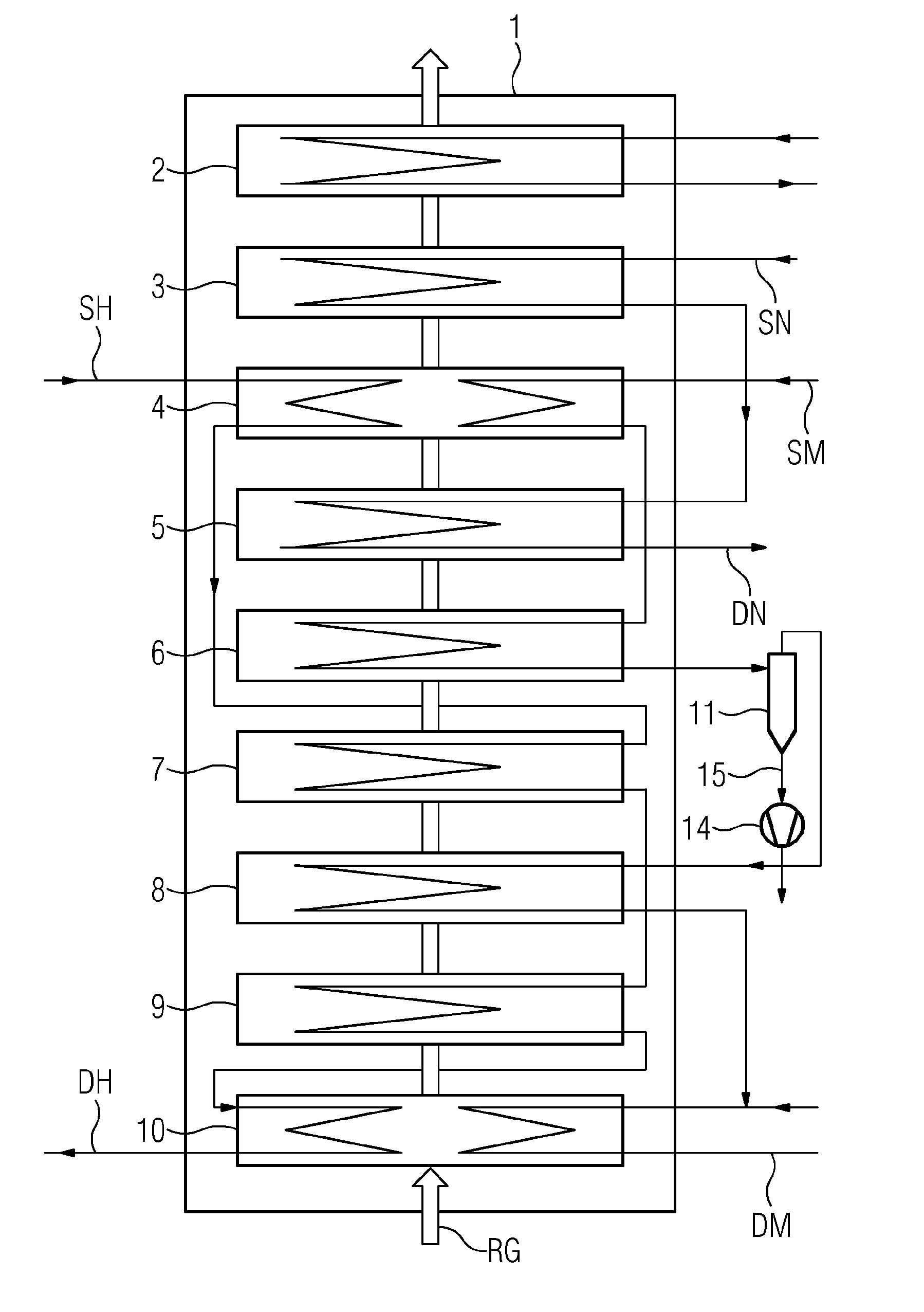
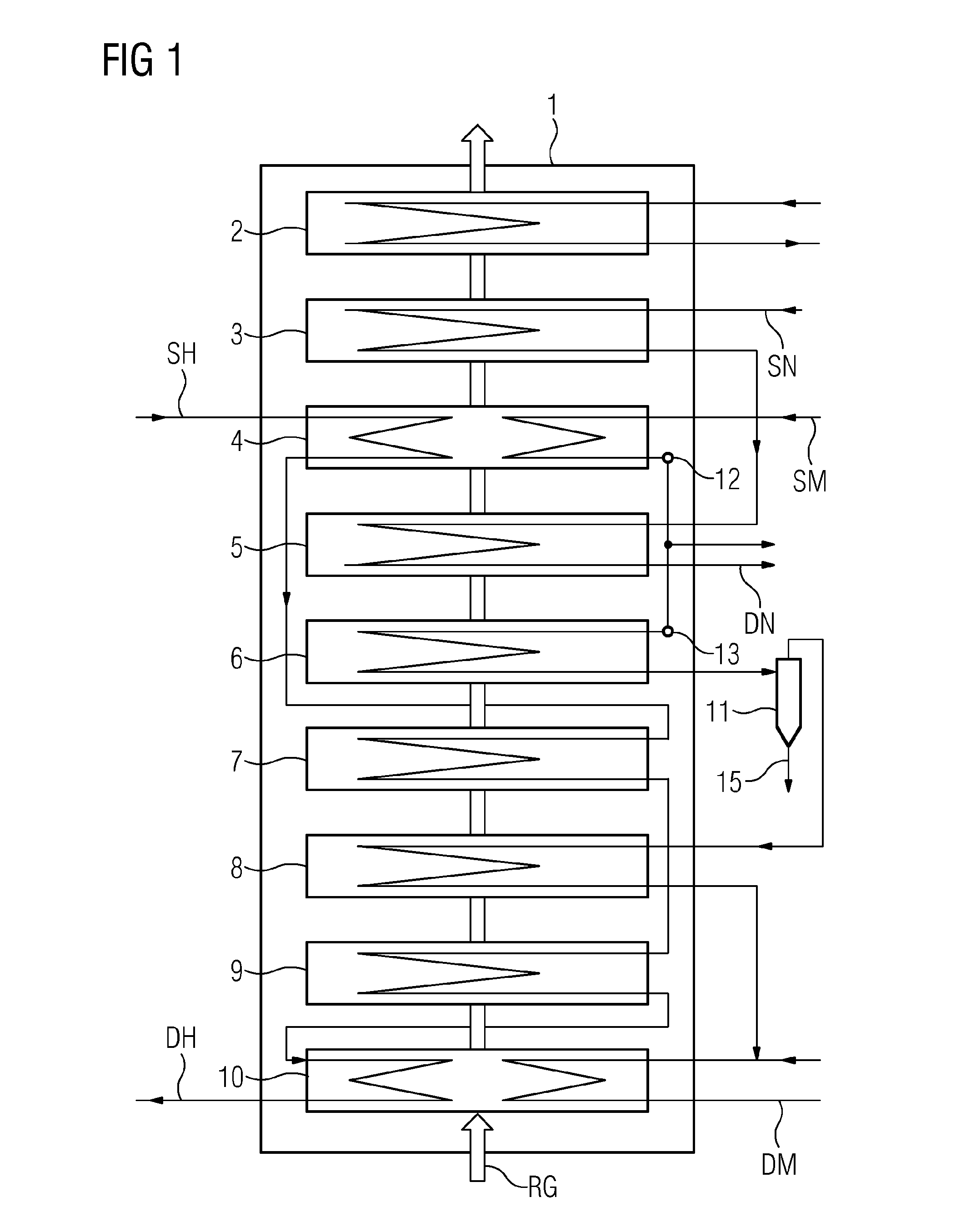
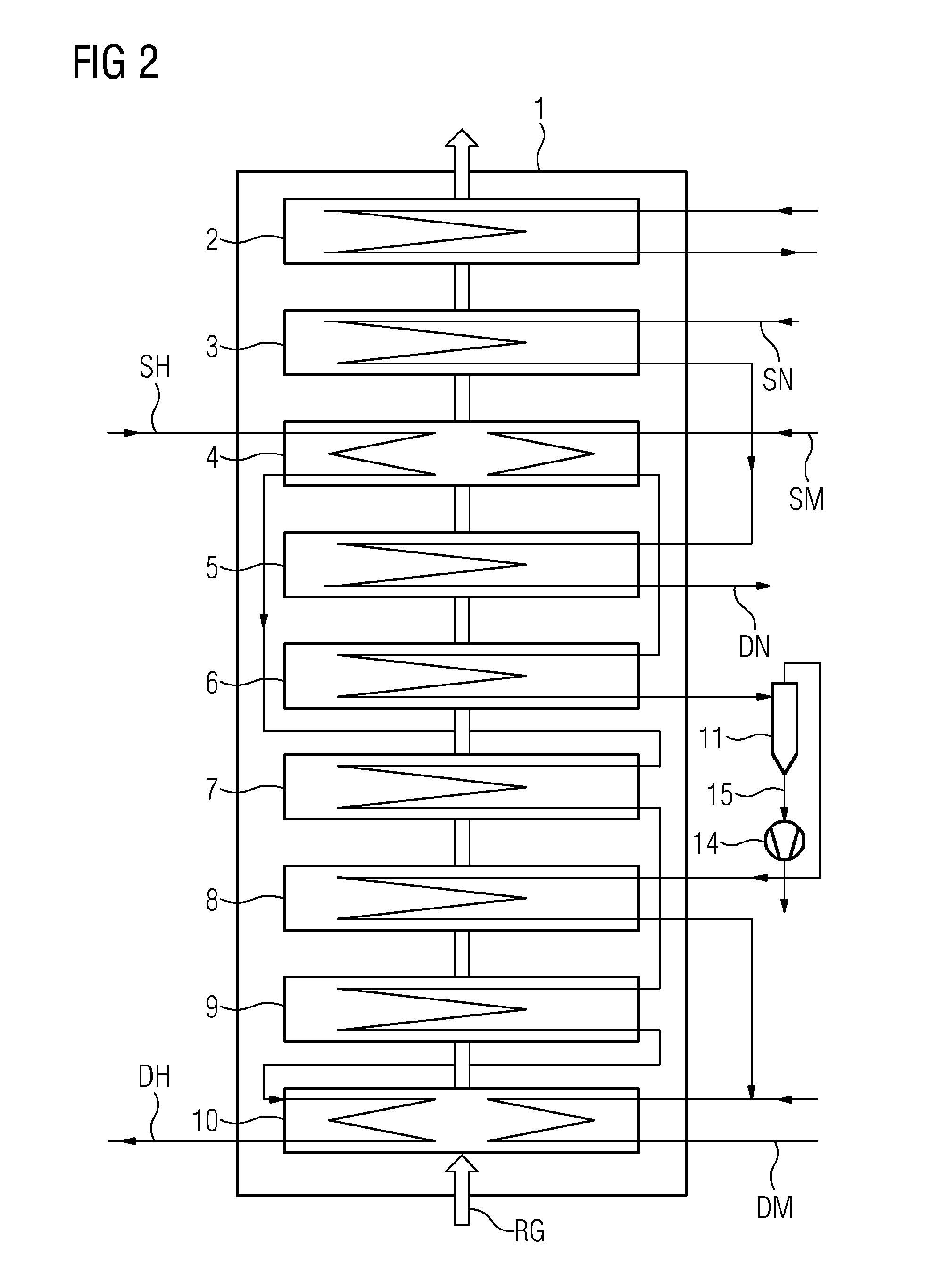
[0019]The waste heat steam generator 1 shown, in upright configuration, is flowed through by hot flue gas RG from the gas turbine. The cooled flue gas RG leaves the waste heat steam generator 1 in the direction of a chimney (not shown in more detail). In the waste heat steam generator, the hot flue gas is used to generate steam for the steam turbine. In that context, the transfer of heat takes place by means of a number of heating surfaces which are arranged in the form of tubes or tube bundles in the waste heat steam generator. These are in turn connected in the water-steam circuit, comprising at least one pressure stage, of the steam turbine. The heating surfaces shown here in the waste heat steam generator form a three-stage pressure system, consisting of a high-pressure stage, an intermediate-pressure stage and a low-pressure stage. In that context, each one of the pressure stages has heating surfaces acting as preheater or economizer, evaporator and superheater, in which feed w...


PUM


Abstract

A combined cycle gas turbine plant and a corresponding method for operating such a combined cycle gas turbine plant, in which, during load operation of the combined cycle gas turbine plant, a water mass flow which is supplied according to the forced-flow principle to a waste heat steam generator is adjusted such that the evaporator heating surface of the medium pressure stage is oversupplied and thus a defined amount of excess water, which is heated in the evaporator heating surface but not vaporized, is discharged via the water-steam separator to a heat exchanger circuit for preheating fuel for the gas turbine.

Description

CROSS REFERENCE TO RELATED APPLICATIONS[0001]This application is the US National Stage of International Application No. PCT / EP2014 / 067830 filed Aug. 21, 2014, and claims the benefit thereof. The International Application claims the benefit of German Application No. DE 102013218809.9 filed Sep. 19, 2013. All of the applications are incorporated by reference herein in their entirety.FIELD OF INVENTION[0002]The invention relates to a combined cycle power plant having a waste heat steam generator, and to a corresponding method for operating such a combined cycle power plant.BACKGROUND OF INVENTION[0003]Combined cycle power plants are installations that combine the principles of a gas turbine power plant and of a steam turbine power plant. In the waste heat steam generator, the hot flue gas leaving the gas turbine is used to generate steam for the steam turbine. In that context, the transfer of heat takes place by means of a number of heating surfaces which are arranged in the form of tu...

Claims


Application Information

Patent Timeline
IPC IPC(8): F01K23/10F02C7/224
CPCF22B1/1815F22B29/06F22B29/068F02C7/224Y02E20/16F01K23/10F01K23/106Y02P80/15
Inventor BRÜCKNER, JANTHOMAS, FRANK
Owner SIEMENS ENERGY GLOBAL GMBH & CO KG
Why Eureka
Try Eureka