
Method for Patterning Using a Composite Pattern

Inactive Publication Date: 2016-08-25
TOKYO ELECTRON LTD
View PDF3 Cites 2 Cited by
  • Summary
  • Abstract
  • Description
  • Claims
  • Application Information

AI Technical Summary

Benefits of technology

The patent text describes methods for improving the process of creating patterns on substrates using plasma processing and photolithography techniques. These techniques can be used to make patterns with greater precision and higher density. The plasma processing can add a protective layer of oxide to the exposed surfaces of a substrate, preventing the material from being dissolved during the process. This allows for the creation of a second layer of patterns on top of the initial layer, doubling the pattern density. The combined pattern can then be used to create subsequent layers on the substrate. Overall, this technology allows for more precise and dense patterning on substrates.

Problems solved by technology

Conventional lithographic techniques for exposing a pattern of radiation or light onto a substrate have various challenges that limit a size of features exposed, and limit pitch or spacing between exposed features.
Conventional LFLE techniques, however, suffer from poor throughput and unacceptable defectivity, among other things.

Method used


Image

  • Method for Patterning Using a Composite Pattern
  • Method for Patterning Using a Composite Pattern
  • Method for Patterning Using a Composite Pattern

Examples


Embodiment Construction

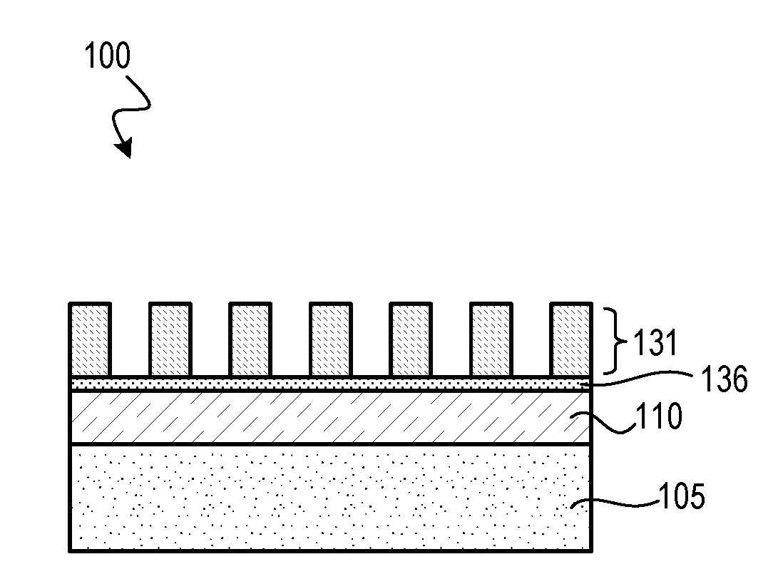
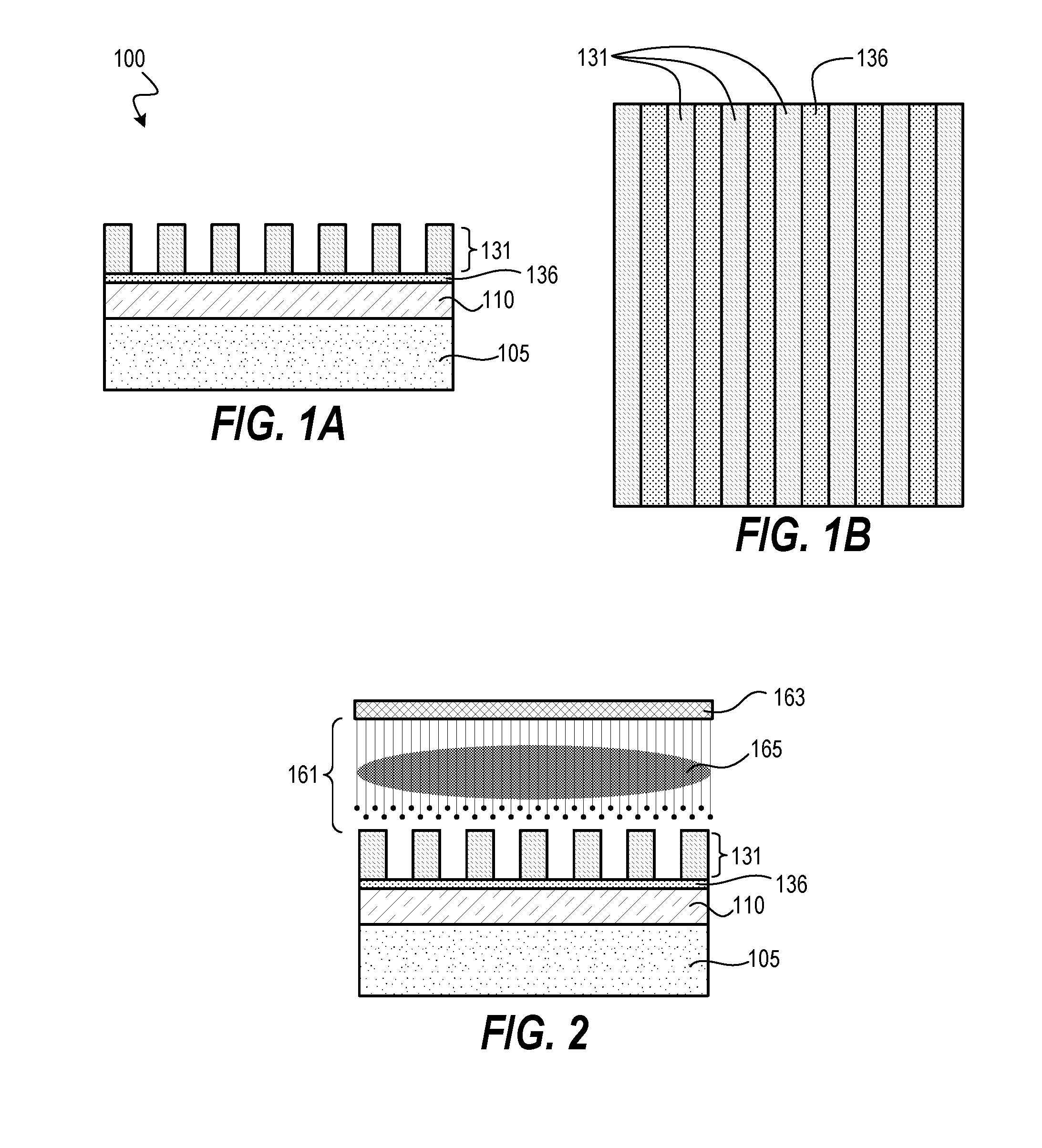
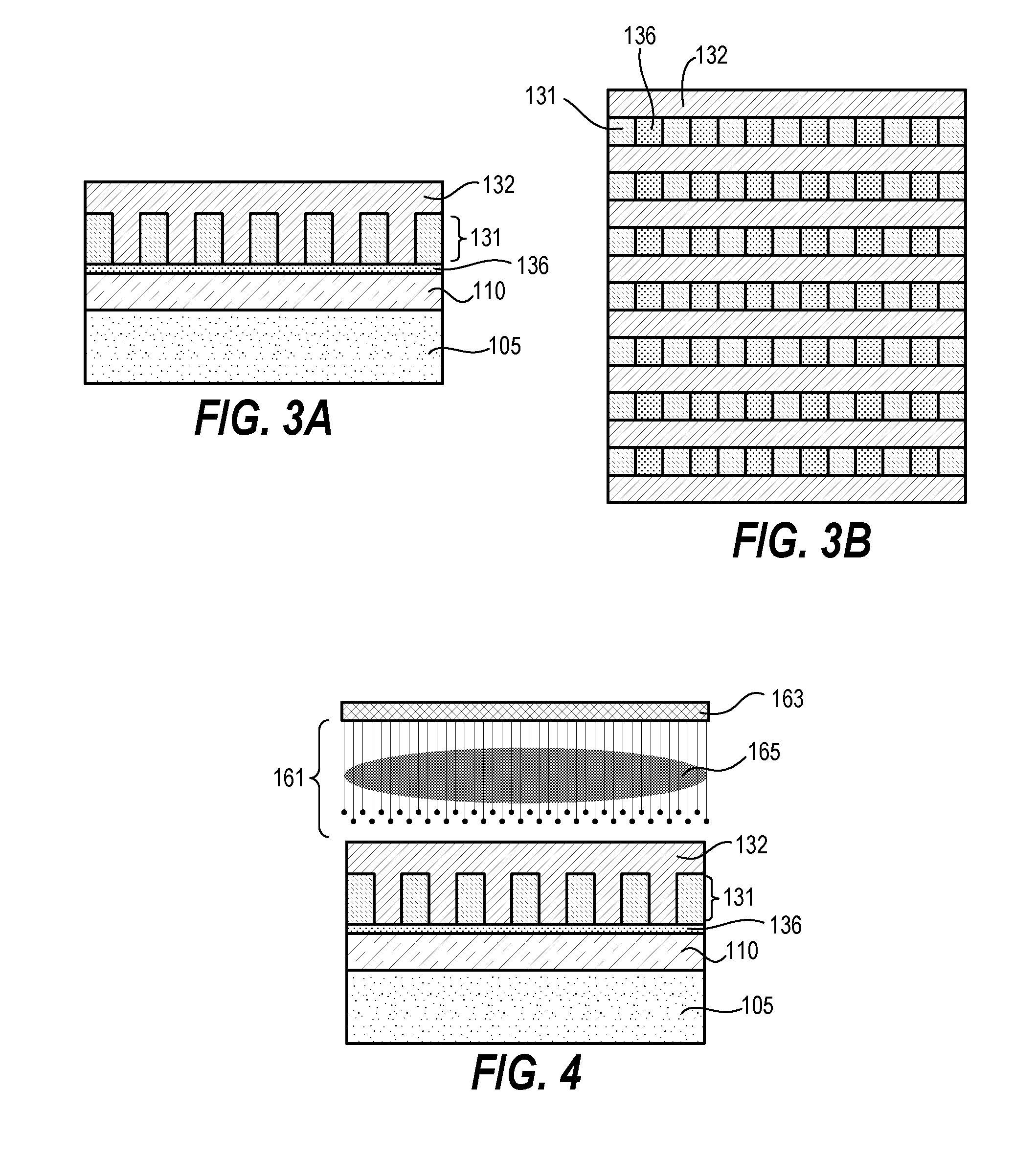
[0026]Systems and methods disclosed herein include improved techniques for patterning substrates, including improvements to double patterning techniques. Techniques herein combine direct current superposition plasma processing with photolithographic patterning techniques. An electron flux or ballistic electron beam herein from plasma processing can induce cross linking in a given photoresist, which alters the photoresist to be resistant to subsequent light exposure and / or developer treatments. Plasma processing can also be used to add a protective layer of oxide on exposed surfaces of a first relief pattern, thereby further protecting the photoresist from a developing acid. By protecting an initial photoresist relief pattern from developing acid, a second relief pattern can be formed on and / or within (between structures of) the first photoresist relief pattern thereby doubling an initial pattern or otherwise increasing pattern density. This second relief pattern can then be treated ...


PUM


Abstract

Techniques herein improved methods for patterning substrates. Techniques herein combine direct current superposition plasma processing with photolithographic patterning techniques. An electron flux or ballistic electron beam herein from plasma processing can induce cross linking in a given photoresist, which alters the photoresist to be resistant to subsequent light exposure and / or developer treatments. An initial relief pattern is treated to become insoluble to developing solvents. A second relief pattern is formed thereon using a same anti-reflective coating. The second relief pattern is also treated to become insoluble to developing solvents. A third relief pattern is then formed on the first and second relief patterns. The three relief patterns form a combined relief pattern without needing a memorization layer.

Description

CROSS REFERENCE TO RELATED APPLICATIONS[0001]The present application claims the benefit of U.S. Provisional Patent Application No. 62 / 119,145, filed on Feb. 21, 2015, entitled “Method for Patterning Using a Composite Pattern,” which is incorporated herein by reference in its entirety.BACKGROUND OF THE INVENTION[0002]This disclosure relates to patterning thin films and various layers on a substrate. Such patterning includes patterning for fabricating semiconductor devices within a photolithographic patterning scheme.[0003]In material processing methodologies (such as photolithography), creating patterned layers comprises the application of a thin layer of radiation-sensitive material, such as photoresist, to a working surface of a substrate. This radiation-sensitive material is transformed into a patterned mask that can be used to etch or transfer a pattern into an underlying layer on a substrate. Patterning of the radiation-sensitive material generally involves exposure by a radiati...

Claims


Application Information

Patent Timeline
IPC IPC(8): G03F7/00G03F7/40G03F7/20G03F7/32H01L21/027H01L21/033
CPCG03F7/0035H01L21/0276H01L21/0335H01L21/0337H01L21/0338G03F7/20G03F7/32G03F7/40H01L21/0273H01L21/31058G03F7/091
Inventor DEVILLIERS, ANTON J.SMITH, JEFFREY
Owner TOKYO ELECTRON LTD
Learn More